Do you have a question about the Armstrong HumidiClean HC-6000 Series and is the answer not in the manual?
| Drain Connection | 1/2" NPT |
|---|---|
| Coverage Area | Varies by configuration |
| Water Usage | 6.0 gallons per hour |
| Voltage | 208-600V |
| Power Consumption | Varies by model |
| Dimensions (H x W x D) | Varies by model |
| Weight | Varies by model |
Critical safety warnings and hazard identifications for humidifier operation.
Specifies electrical and environmental requirements for safe humidifier installation.
Explains the series and model number designation for the humidifiers.
Covers initial checks like shipment, local codes, and site selection.
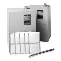
Illustrates steam and drain piping for HC-6100/6300 models.
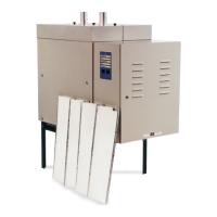
Illustrates steam and drain piping for HC-6500/6700 models.
Instructions for wall mounting HC-6100 and HC-6300 models.
Instructions for floor mounting HC-6500 and HC-6700 models.
Specifies water supply requirements and guidelines for electrical service wiring.
Instructions for connecting the drain and managing hot drain water.
Details on installing dispersion tubes and managing airflow in ducts.
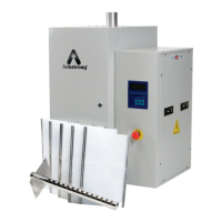
Information on fan packages for remote area discharge.
Guidelines for low voltage control wiring and IP65 compliance.
Instructions for locating and setting up humidistats and DIP switches.
Explains high limit humidistats, airflow/pressure switches, and alarm circuits.
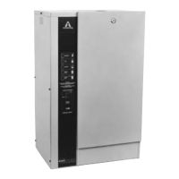
Overview of the unit's display menus and setup options like mode, PID, and drain settings.
Configuration of network mode, aquastat, EOL, and calibration settings.
Configuration steps for connecting via Modbus RS485.
Instructions for connecting the LonWorks protocessor.
Configuration steps for BACnet MSTP and IP protocols.
Instructions for sending percent output commands via communication ports.
Mapping of BACnet addresses to data points and their attributes.
Mapping of Modbus addresses to data points and their function numbers.
Continued mapping of Modbus addresses to data points.
Configuration table for dip switch settings based on communication profiles.
Continuation of the dip switch configuration table.
Continuation of the dip switch configuration table.
Continuation of the dip switch configuration table.
Step-by-step guide for initial start-up and normal operating principles.
Procedures for servicing the unit, including cleaning and component checks.
Procedures for draining the unit at season end and replacing ionic beds.
Detailed steps for cleaning the water level probes and canister.
A checklist to ensure proper installation and configuration before operation.
Final steps and verification before powering on the unit.
Diagnoses common problems like no fill, low steam output, overfilling, and water issues.
Explains error codes, diagnostic routines, and safety switch indicators.
Electrical wiring diagrams for various model configurations.
Lists electrical and water compartment parts with part numbers for different models.
Tables detailing heating element part numbers by voltage and kW.
Resistance values for key components for troubleshooting.
Explanation and tuning of Proportional, Integral, Derivative, and SI parameters.
Procedure for refreshing the PCB-1 board's firmware.
Physical dimensions and weight specifications for the humidifier models.
Outlines the warranty terms, limitations, and remedy procedures.