Do you have a question about the Art HQ 231 and is the answer not in the manual?
Explains the Feedback Detection Circuit (FDC) feature, how it works, and its benefits for identifying feedback frequencies.
Details how FDC can be used as a spectrum analyzer to identify room modes and potential feedback in live sound systems.
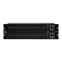
Describes the physical dimensions and rack-mounting capabilities of the equalizer.
Details the power requirements and voltage selection for the equalizer.
Explains the types of input/output connectors (XLR, 1/4", RCA) and their wiring for balanced/unbalanced connections.
Defines normal signal levels and advises against connecting microphones directly without a preamp.
Discusses grounding issues, the ground lift switch, and potential causes of hum or buzzing.
Offers step-by-step instructions for the initial setup and configuration of the equalizer.
Instructions for turning the equalizer on and off, with a caution about amplifier power sequencing.
Explains the function of the sliders that control the output level of the 31 bandpass filters.
Describes the switchable gain range (+/- 6dB or +/- 12dB) and its associated LED indicators.
Explains the bypass switch for comparing signals and the clip LED as a clipping warning.
Details the High-Pass Filter control for reducing unwanted low frequencies and its frequency range.
Explains the Low-Pass Filter control for reducing unwanted high frequencies and its frequency range.
Describes the input level control and how to set unity gain, with guidance on avoiding clipping.
Explains the Feedback Detection Circuit LEDs and how they indicate feedback levels.
Describes the LED level meter for monitoring output levels and setting proper signal levels.
Information about the AC power cord, including safety precautions for USA installations.
Explains the fuse holder, fuse types, and replacement procedures, including voltage-specific fuses.
Instructions for selecting the correct AC voltage supply for the unit.
Explains the function of the ground lift switch for mitigating hum caused by ground loops.
Provides detailed specifications and wiring information for 1/4" TRS, XLR, and RCA connectors.
Details the duration and conditions of the product warranty provided by the manufacturer.
Lists conditions under which the warranty is void, such as misuse or unauthorized modifications.
| Brand | Art |
|---|---|
| Model | HQ 231 |
| Category | Stereo Equalizer |
| Language | English |