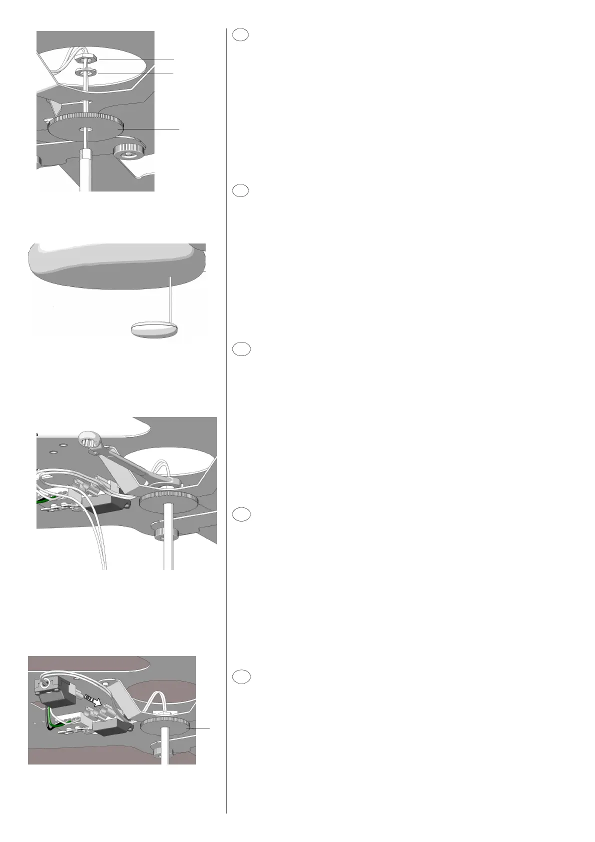
Avvitare fino in fondo la manopola D sull’estremità filettata.
Far scorrere sul cavo il dado E e la rondella dentellata F fino a toccare il connettore (fig. 14).
Infilare il cavo elettrico nell’apposito scasso posto sul supporto di fissaggio. Inserire l’astina
di sostegno nell’apposita sede sagomata del supporto in modo che il corpo illuminante sia
disposto come in figura 15.
Mantenendo il corpo illuminante in posizione, far scorrere la rondella dentellata ed il dado,
quindi avvitarlo a mano all’astina di sostegno.
Mediante la chiave in dotazione completare il fissaggio senza serrare a fondo il dado per
evitare eventuali danneggiamenti della struttura (fig. 16).
Svitare la manopola D fino a bloccarla contro il supporto.
Eseguire il collegamento elettrico connettendo i due spinotti (fig. 17).
~
D
~
~
E
F
fig. 14
fig. 15
fig. 16
fig. 17
~
D
I
F
EN
D
E
Atornillar completamente el mango D en la extremidad roscada.
Hacer deslizar la tuerca E y la arandela dentada F sobre el cable hasta tocar el conector (fig.
14). Introducir el cable eléctrico en la abertura adecuada en el soporte de fijación. Introducir
la varilla de soporte en el espacio correspondiente del soporte para que el cuerpo de
iluminación se encuentre en la posición indicada en la figura 15.
Manteniendo el cuerpo de iluminación en su posición, hacer deslizar la arandela dentada y
la tuerca; sucesivamente, atornillarlo manualmente a la varilla de soporte.
Mediante la llave entregada, completar la fijación sin apretar completamente la tuerca para
evitar dañar la estructura (fig. 16).
Destornillar el mango D hasta bloquearlo contra el soporte.
Efectuar la conexión eléctrica conectando los dos enchufes (fig. 17).
Visser complètement la poignée D sur l’extrémité filetée.
Faire glisser l’écrou E et la rondelle dentée F sur le câble jusqu’à toucher le connecteur (fig.
14). Insérer le câble électrique dans l’ouverture adéquate placée sur le support de fixation.
Insérer la tige de support dans le logement adéquat profilé du support de façon que le corps
d’éclairage soit positionné comme indiqué dans la figure 15.
En tenant le corps d’éclairage en position, faire glisser la rondelle dentée et l’écrou, ensuite
le visser manuellement à la tige de support.
A l’aide de la clé fournie compléter la fixation sans serrer complètement l’écrou afin d’éviter
des endommagements éventuels de la structure (fig. 16).
Dévisser la poignée D jusqu’à la bloquer contre le support.
Brancher en connectant les deux broches (fig. 17).
Completely screw knob D on the threaded end.
Make nut E and notched washer F slide on the cable until they touch the connector (fig.
14). Insert the electric cable in the proper opening located on the fixing support. Insert the
supporting rod in the proper shaped seat of the support so that the illuminating body is
positioned as indicated in figure 15.
While holding the illuminating body in the correct position, make the notched washer and
the nut slide, then screw it by hand to the supporting rod.
Complete the fixing operation by means of the supplied key without completely tighening
the nut in order to avoid damaging the structure (fig. 16).
Unscrew knob D until it is locked against the support.
Carry out the electric connection by connecting the two plugs (fig. 17).
Den Knopf D auf dem geschnittenen Ende vollständig anschrauben.
Die Mutter E und die gezähnte Unterlegscheibe F auf dem Kabel gleiten lassen, bis sie den
Stecker (Abb. 14) erreichen. Das elektrische Kabel in die dazu bestimmte Öffnung auf der
Befestigungsstütze einziehen. Die Stützstange in den dazu bestimmten profilierten Sitz der
Stütze so stecken, dass der Beleuchtungskörper wie in Abbildung 15 positioniert ist. Den
Beleuchtungskörper in der richtigen Position halten, die gezähnte Unterlegscheibe und die
Mutter gleiten lassen und dann an der Stützstange manuell anschrauben
Die Mutter durch den mitgelieferten Schlüssel nicht vollständig anschrauben (Abb. 16), um
zu vermeiden, die Struktur zu beschädigen.
Den Knopf D abschrauben, bis er gegen die Stütze blöckiert wird.
Die zwei Stecker (Abb. 17) verbinden.
 Loading...