Do you have a question about the Artesyn ATCA-F140 and is the answer not in the manual?
Precautions for preventing circuit damage during installation and handling.
Safety guidelines for operating the device, including overheating and blade damage.
Safety guidelines for handling SFP/SFP+/QSFP+ modules, including eye safety.
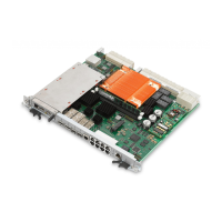
Overview of the key features and specifications of the ATCA-F140.
Procedures for installing and removing the ATCA-F140 blade.
Step-by-step instructions for installing the blade into an ATCA shelf.
Step-by-step instructions for safely removing the blade from an ATCA system.
Procedures for installing and removing AMC modules in the AMC bay.
Instructions for installing and removing SFP modules.
Procedure for correctly installing an SFP module into its slot.
Procedure for correctly removing an SFP module from its slot.
Instructions for installing and removing QSFP+ transceiver modules.
Procedure for correctly installing QSFP+ transceiver modules.
Procedure for correctly removing QSFP+ transceiver modules.
Pinout assignment for the AMC bay connector.
High-level functional view of the ATCA-F140 board and its interfaces.
Details on the Freescale P2020 QorIQ processor and its features.
Details on the Intelligent Platform Management Interface implementation.
Description of the ATCA-F140's base channel interface using Broadcom BCM56334.
Details on the Broadcom PHYs used for the base channel interface.
Information on SFP+ and QSFP+ module receptacles and their functions.
Details on SFP+ module signals, interfaces, and tested modules.
Details on QSFP+ module signals, interfaces, and tested modules/cables.
Details the reset domain for the service processor core.
Explanation of the hard and soft reset signals for the service processor.
Methods for configuring U-Boot boot behavior.
Procedure to configure U-Boot for booting from a TFTP server.
Procedure to configure U-Boot for booting from a RAM disk image.
Procedure to configure U-Boot to boot from onboard flash memory.
Details the specific POST routines performed on the device.
Procedures and precautions for replacing the device battery.