EasyManua.ls Logo

Arzel 1200 Series - User Manual

Default Icon
6 pages
Print Icon
To Next Page IconTo Next Page
Loading...
1
Arzel® Zoning Technology
(AirBoss™ and 1200 Series Panels)
Troubleshooting Guide
1) VOLTAGE TEST
a) 24 Volt AC
i) Check AC voltage at 24-VAC R & C terminals, no less than 21.6 Volts A/C
should be present from Arzel supplied Transformer
(40 VA for 2, 3, and 4 zone panels)
(100 VA for 6 and 8 zone panels)
b) 24 Volt DC
i) Generate a call for “Y1”, “Y2” & “G” at zone 1 only (use jumpers if needed),
and set all other zones to “Auto Fan” and “Off”. (This will energize all but
one solenoid and put the board under its heaviest load)
ii) With board under full load, there should be no less than 24 Volts DC between
(SOLENOID “ + “) and (BYPASS “ D “) terminals
iii) If 24 Volts AC is present at 24VAC terminals and the DC Volts is less than
24, the board will need replaced
2) TESTING BOARD “OUTPUT” (EQUIPMENT FUNCTION) RELAYS.
a) Turn “Power” switch “ON” (Red LED On) and call for Heat from one or more
thermostats;
i) Is the Red “W1” LED lit at the “HVAC OUTPUT” terminal?
(1) Yes!
LED is on
(a) Check for continuity (0 Ohms) between the “R” and “W1” terminals at
the “HVAC OUTPUT” terminal strip on Arzel board (wires removed).
(b) If no continuity ( ohms), the board must be replaced.
(c) If continuity is present (0 ohms), the board is OK and the problem is
with the HVAC equipment or a faulty wire between panel and
equipment.
(i) Turn panel Power switch “OFF” and Check voltage (A/C) between
HVAC Output “R” & “W” terminals (wires connected).
(ii) No Voltage indicates problem with equipment control power or
wiring.
(2) No! LED is not lit - Check for 24v ac between “W1” and “C” terminals at
the calling zone terminals.
(“W1” with an “O” is an illegal call and will be ignored)
(“W2” without a “W1” is an illegal call and will be ignored)
Question and Answer IconNeed help?

Do you have a question about the Arzel 1200 Series and is the answer not in the manual?

Overview

This document is a troubleshooting and preventive maintenance guide for Arzel® Zoning Technology, specifically for AirBoss™ and 1200 Series Panels. It covers various aspects of the system, including voltage tests, board output relays, damper operation, solenoid testing, air side integrity checks, LAT (Leaving Air Temperature) operation, and bypass operation.

Function Description:

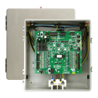
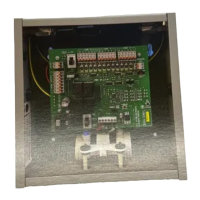
The Arzel Zoning Technology system is designed to manage and control HVAC (Heating, Ventilation, and Air Conditioning) in different zones of a building. It utilizes a control panel to regulate dampers and equipment functions based on thermostat calls from individual zones. The system aims to optimize comfort and energy efficiency by directing conditioned air only to areas that require it. Key components include the control panel, thermostats, dampers, solenoids, and a transformer.

Important Technical Specifications:

Voltage Test:

  • 24 Volt AC:
    • Minimum 21.6 Volts A/C should be present at 24-VAC R & C terminals from the Arzel-supplied transformer.
    • Transformer ratings: 40 VA for 2, 3, and 4 zone panels; 100 VA for 6 and 8 zone panels.
  • 24 Volt DC:
    • With the board under full load (zone 1 calling for Y1, Y2, G; all other zones set to "Auto Fan" and "Off"), there should be no less than 24 Volts DC between SOLENOID "+" and BYPASS "D" terminals.
    • If 24 Volts AC is present but DC Volts is less than 24, the board needs replacement.

Board Output (Equipment Function) Relays:

  • Continuity (0 Ohms) should be present between "R" and "W1" terminals at the HVAC OUTPUT terminal strip when the "W1" LED is lit.
  • No continuity (∞ ohms) indicates a faulty board.
  • If no voltage (A/C) is present between HVAC Output "R" & "W" terminals (wires connected) when the panel power switch is OFF, it indicates a problem with equipment control power or wiring.

Damper Operation:

  • Normal press/vac reading for damper actuators: approximately 30-40 in. wc. (1-2 psi).
  • To close a damper: requires a positive pressure of at least 25" wc.
  • To open a damper: requires a vacuum of at least -25" wc.

Solenoid Testing:

  • 24 V DC: Should be present between solenoid terminals (+) and (2, 3, & 4) when Zone 1 is calling for Fan (G) and all other zones are off. This energizes solenoids to create pressure and close dampers.
  • 0 V DC: Should be present between solenoid terminals (+) and (1) under the same conditions. This de-energizes solenoids to create vacuum and open dampers.
  • Ohm Test: Disconnect the solenoid lead from its numbered "SOLENOID" terminal. Read across the loose lead and "+" terminal. Ohms should be between 850 and 950 ohms.

LAT Operation (Heating):

  • Heating LAT set point should maintain supply air temperatures within furnace manufacturers' specifications.
  • To calculate the Htg LAT setting: Add 70 deg (typical return air temperature) to the maximum specified temperature rise. Example: If the specified temperature rise is "35 to 60 deg", the Htg LAT setting should be 130 deg.

LAT Operation (Cooling):

  • Start with a cooling LAT setting of 42 deg and raise 2 deg at a time if the DX Coil shows signs of icing.
  • The LAT Sensor should be located in the supply duct (not in the plenum), prior to any trunk dampers, and in a duct common to all zones. If in a teed duct, place it on the side with the Bypass or smallest cooling Zone.

Sensor Calibration and LAT Voltage:

  • With the sensor disconnected from the board:
    • Resistance: Approximately 11,000-13,000 ohms at 72 to 66 deg.
    • Voltage: Approximately 4.9 volts DC (+/- 0.2 volts).
  • With the sensor connected to the board:
    • Voltage: Approximately 3 volts DC @ 70 supply air temperature.

Bypass Operation and Remedies:

  • Blower speed adjustment: Check and adjust CFM output of the blower (400 to 300 cfm / ton).

Usage Features:

  • Master Zone Control Function: When the Master Zone Control switch is "On," only Zone #1 calls for system functions (heat, cool, or fan). LEDs for other calling zones will illuminate, but not the HVAC OUTPUT or Zone Solenoid LEDs. All zone solenoid LEDs will illuminate, and dampers will open when Zone #1 calls.
  • Airflow Indicator: An open-ended "Airflow Indicator" (available through Arzel) is used to visually confirm pressure (ball lifts to top) or vacuum (ball lifts to top of cylinder) at solenoid ports.
  • Troubleshooting Steps: The guide provides systematic steps for diagnosing issues, including checking voltage, continuity, and physical operation of components.

Maintenance Features:

  • Preventive Maintenance Guide: The document also serves as a preventive maintenance guide, outlining checks for solenoid/pump operation, air side integrity, and LAT operation.
  • Air Side Integrity Check:
    • Use the Arzel "Air Flow Indicator" to detect air leaks in tubing or damper actuators.
    • Individual damper actuator leakage check involves disconnecting the tube, removing the damper from the duct, moving the blade to the closed position, holding a finger over the tube port, and then moving the blade to the open position. Pressure build-up should impede opening; if it subsides, the actuator is leaking.
  • Solenoid/Pump Operation Check: Verify proper pressure or vacuum to a damper by inserting a tee in the tube and reading with a Magnehelic or Digital pressure gauge.
  • LAT Operation Checks: Regularly check if the furnace is cycling on an internal limit or if the LAT is cycling equipment off and on unnecessarily. This involves checking for oversized bypass ducts and adjusting LAT set points.
  • Bypass Operation Checks: Periodically check bypass operation with the smallest and largest zones calling to ensure it only opens when air noise is an issue during cooling with other zones satisfied.
  • Solenoid "Bleed Through" Test: To test for "Bleed Through," remove the vacuum hose (n/o port) from each solenoid, plug the disconnected tube and the open port. If remaining zones operate properly, the solenoid is faulty.
  • Tube Port Restriction Check: Inspect inside the top solenoid port for any objects restricting airflow to dampers.

The guide emphasizes the importance of proper installation and adjustment of components like bypass ducts and LAT settings to ensure optimal system performance and prevent issues like air surging noise, freezing coils, or nuisance tripping. It also provides a technical support hotline for further assistance.

Arzel 1200 Series Specifications

General IconGeneral
BrandArzel
Model1200 Series
CategoryControl Panel
LanguageEnglish

Related product manuals