Page 4 of 4 I&M No. V_5436_R13
©
ASCO Valve, Inc.
50 Hanover Road, Florham Park, New Jersey 07932 www.ascovalve.com
IMPORTANT
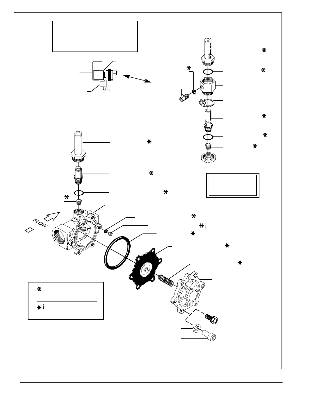
sub-assembly must be located on
Captive spacer on stem/spacer
the outside of stem retainer
when reassembled.
stem/spacer
sub-assembly
stem retainer
valve seat
Indicates Parts Supplied
In ASCO Rebuild Kits
¡
This part is NOT
supplied in all kits
spacer
MANUAL OPERATOR
(OPTIONAL)
stem gasket
stem/spacer
sub-assembly
solenoid base
sub-assembly
core assembly
with core
spring
solenoid base gasket
valve body
body passage gasket
body passage eyelet
solenoid base
sub-assembly
solenoid base
manual operator
body
gasket
stem retainer
core assembly
with core spring
bonnet gasket
valve seat
PARTIAL VIEW
IMPORTANT
See torque
chart
¡
body gasket
diaphragm assembly
For stainless steel valves: washer (4)
For stainless steel valves: socket head screws (4)
diaphragm spring
valve bonnet
For brass valves:
bonnet screw (4)
hex head
Figure 2. Series 8210 valve without solenoid, DC construction with 1 ½" NPT valve body shown.
Note:
Constructions with “LF” sufx
will be identied with “LF” mark
on body and bonnet.
 Loading...