Page 3 of 4Form No.V8700R1
50-60 Hanover Road, Florham Park, New Jersey 07932 www.ascovalve.com
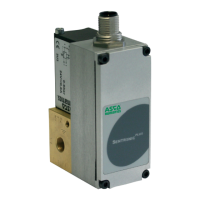
Auxiliary Switch Adjustment
1. Remove the window (Figure 4).
2. Loosen the camlock screw no more than 1/2 turn.
3. Reset the cam adjustment screw to the desired switching
point.
4. Tighten the camlock screw. Cycle the actuator to verify
the switch setting and readjust as required.
5. Reinstall the window and torque screws evenly to 14-16
in-lbs [1,6-1,8 Nm].
Figure 4. Auxiliary Switch Adjustment
MAINTENANCE
Maintenance should include periodic inspection and cleaning.
Use a cleaning fluid compatible with actuator components to
remove dirt and oil. Organize a maintenance schedule based
on environment and frequency of use. Check for loose
electrical and mechanical connections and replace damaged
lead wires.
Field Service Notice
Field service replacement kits are limited to the following:
1. Travel limit switch Replacement Kit 440000 (AH2D).
2. Left-hand auxiliary switch Replacement Kit 440002.
3. Right-hand auxiliary switch Replacement Kit 440003.
4. Overtravel proof-of-closure switch Replacement Kit
440004. See separate AH series actuator overtravel
proof-of-closure switch replacement kit installation
instructions.
5. Damper shaft Replacement Kit 440005.
6. Damper arm Replacement Kit 440006 (with spring and
spring plug) or 440007 (without spring and spring plug).
7. Oil Replacement Kit 440008.
To order, specify the kit or part number, as well as the actuator
model and serial numbers.
Travel Limit Switch Replacement
1. Remove the six cover screws and the cover plate
(Figure 1)
2. Disconnect actuator and switch wiring. Remove two
mounting screws and the limit switch (Figure 2).
3. Install the new switch and reconnect wiring. The required
stroke is 1 1/8I ± 1/16I. Turn adjustment screw located
above limit switch until the desired stroke is achieved.
Turn the adjustment screw clockwise to decrease stroke
and counterclockwise to increase stroke. Operate the
actuator a few times to verify proper adjustment.
4. Reinstall the cover plate and screws.
Auxiliary Switch Replacement
1. Remove six cover screws and the cover plate (Figure 1).
2. Disconnect switch wiring. Remove two mounting screws
and old switch wiring and install new switch.
3. Wire and adjust switch as instructed under Switch
Adjustment.
4. Install actuator on valve and torque set screws to 80 ± 5
in-lbs [9,0 ± 0,5 Nm] using a 5/32I hex key wrench.
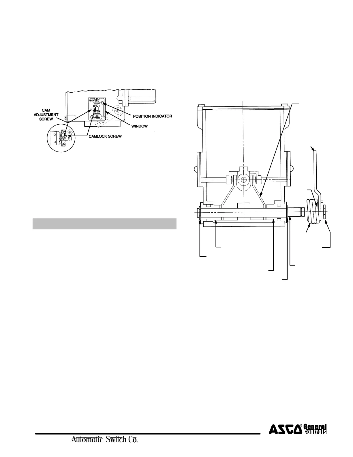
BUSHING (2)
RETAINING RING (1)
DAMPER
RETAINING
RING (6)
SHAFT (3)
RETAINING
RING (6)
SPRING (8)
SPRING
PLUG (9)
DAMPER
DAMPER ARM
POSITIONER (4)
ARM (7)
Figure 5. Damper Shaft and Damper Arm Kits
BUSHING (5)
Damper Shaft Installation (Figure 5)
The damper shaft can be installed with the damper arm on
either side of the actuator.
1. Loosen the two mounting set screw (Figure 2) and lift the
actuator from the valve.
2. Install the retaining ring (1) and bushing (2) on the
damper shaft (3).
3. Install the damper arm positioner (4), then slide the
damper shaft (3) through the actuator and positioner.
4. Install bushing (5) and secure with retaining ring (6).
5. Reconnect the wiring, restore power, and cycle the
actuator to verify proper operation.
 Loading...