Operator’s Series 300
Manual Generator Paralleling System
Call 1 800 800-2726 (ASCO) for sales or service
Florham Park, NJ 07932-1591 USA
+Before reading please note the following
:
DANGER is used in this manual to warn of a
hazardous situation which, if not avoided,
will result in death or serious injury.
WARNING is used in this manual to warn of a
hazardous situation which, if not avoided,
could result in death or serious injury
.
CAUTION is used in this manual to warn of a
hazardous situation which, if not avoided,
could result in minor or moderate injury
.
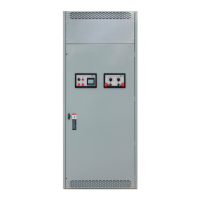
Figure 1: (2)-Generator System
All service to this equipment should be provided
only by a qualified service technician. No work
should be attempted without complete
documentation, including but not limited to
drawings, manuals, and interconnect
information.
For service and support, call 800-800-ASCO (800
800 2726) or email customercare@asco.com
Rating Label
Each ASCO Series 300 Power Control System
(PCS) contains a rating label to define the loads
and withstand/closing ratings. Refer to the label
on the unit for specific values.
For a non-redundant system where the load
current is more than one generator’s full load
current and the generators are paralleled to
provide more power to the load, the main bus
current rating must be equal to or greater than the
sum of the two generator’s full load amps.
If the application is a redundant system where the
load current is equal to or less than the full load
amps of one generator and the generators are
being paralleled for redundancy, the rating must
be equal to or greater than the full load current of
the biggest generator. In addition, the output
circuit breaker must have proper overcurrent
protection, equal to or less than the main bus
rating label.
Do not exceed the values on the rating label.
Exceeding the rating can cause personal injury
and/or serious equipment damage.
381333-453