2 of 5
P/N PM000199A • Rev. 3 • ISS 25APR2018
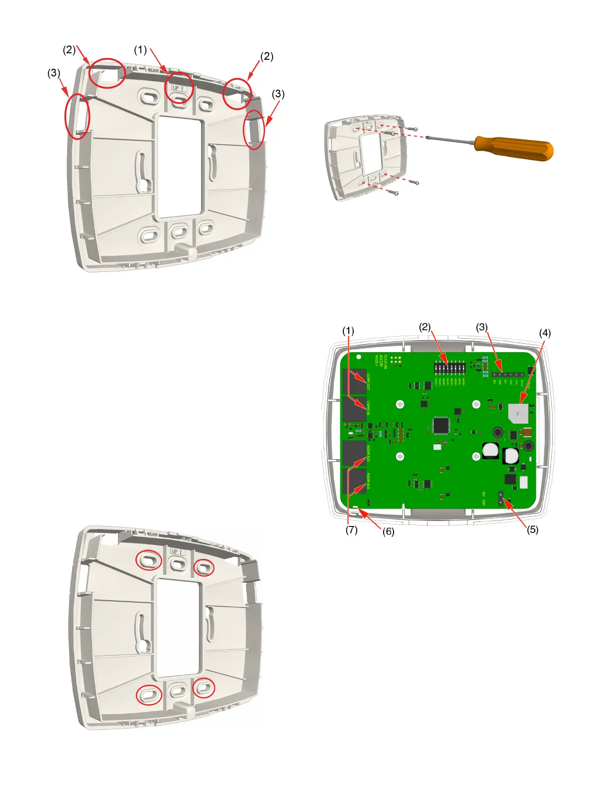
Figure 1: Backplate directional arrow and knockouts
Legend
(1) Arrow indicator
(2) Top knockouts
(3) Side knockouts
To remove the knockouts:
1. Locate the knockouts to be removed from the top or sides
of the backplate. See Figure 1, items 2 and 3.
2. Using a cutter or pliers, carefully remove the excess plastic
from the knockouts.
To mount a backplate spacer on a wall:
1. Place the backplate spacer against a flat wall and orient it
so that arrow is pointing up and that the backplate is level.
(See Figure 1, item 1.) Use a leveling device to check, if
necessary.
2. Using the backplate spacer as a template, mark four holes
for the screws using the fitting holes located in the
backplate spacer.
3. Remove the backplate spacer and drill holes for the
screws that will be used, such as wood, concrete, or
drywall screws, or screws with anchors.
4. Place the backplate spacer (with the knockouts
removed) over the holes, insert the screws, and then
tighten.
5. Pull the cables through the knockout holes.
Connections and DIP Switch Settings
Before attaching the dome light to its backplate, make all
wire connections and set the DIP switches. Be sure that
each cable is properly terminated. The figure below shows
the terminating locations for each cable.
Figure 2: NUDL-series dome light connections
Legend
(1) 2x RJ-45 connection to hallway bus
(2) DIP switches for hallway bus addressing
(3) Auxiliary I/O terminal for auxiliary inputs
(4) Buzzer
(5) 36VDC power connection
(6) Status LED
(7) 2x RJ-45 connections to active room buses
Setting the Hallway Bus Address
The dome light connects to an active hallway bus. Hallway
bus addressing can be handled in either of two ways, using
the System Configuration Tool, or using DIP switches. When
setting the address using the System Configuration Tool,
all DIP switches on the device must be set to “0” (OFF).
 Loading...