P/N PM000199A • Rev. 3 • ISS 25APR2018
3 of 5
When using DIP switches for hallway bus addressing, all
attached hallway devices must be addressed using their DIP
switches.
Determine the bus address for your dome light before setting
the DIP switches. If you are unsure of the device’s address,
check with your system designer. The default setting for all
DIP switches is “0” (OFF).
When replacing dome lights that are addressed with DIP
switches, copy the DIP settings to the new device. If the DIP
switches were not used for addressing, be sure all the DIP
switches are in the OFF position on the back of the module.
Next, configure the device using the System Configuration
Tool to activate the replacement unit in the system.
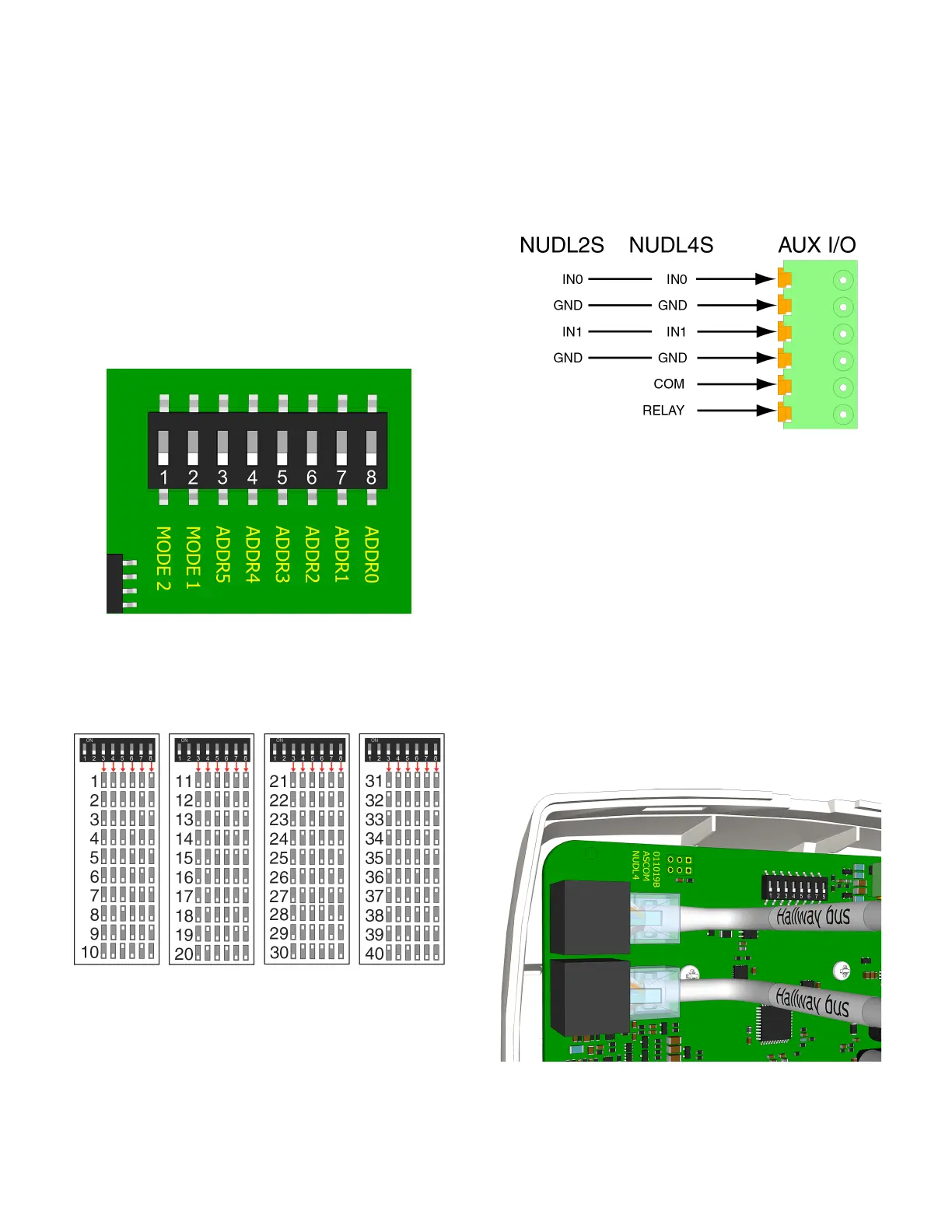
The following figure illustrates the DIP switches found on the
back of a hallway device.
Figure 3: DIP switches on the dome light (default OFF)
The following table shows the DIP switch settings for all
addresses.
Note: DIP switches 1 and 2 are mode switches and must
remain in their default positions (OFF).
Table 1: DIP switch settings for all hallway bus addresses
To set a DIP switch:
1. Set the DIP switches to the address chosen for the dome
light. Use the address table above to determine the
correction positions (ON or OFF) for the DIP switches.
2. Using a small screwdriver, gently slide the switch up for
“ON” or slide it down for “OFF.”
To terminate a 4-pole or 6-pole connector for an auxiliary
I/O cable:
1. Terminate the auxiliary I/O cable with a 4-pole connector,
or a 6-pole connector, as required.
Note: You must use the 4-pole connector (P/N NICT-4AA)
with the NUDL2SH and the 6-pole connector
(P/N NICT-6AA) with the NUDL4S-H. The connectors are
not included.
To connect a dome light:
1. Set the dome light’s DIP switches according to your
installation’s bus addressing scheme. See the Figure 2,
item 2.
Note: If your installation does not require DIP switches,
skip this step and use the Software Configuration Tool.
The DIP switches must remain in their OFF position.
2. If you are connecting an auxiliary I/O to the dome light,
terminate the wires from the auxiliary device to the proper
terminals on the 4- or 6-pole connector; otherwise, skip
this step. Ensure the connector is seated properly on the
terminal pins. See Figure 2, item 3.
3. Insert the RJ-45 connector from the hallway bus (IN) into
the COMM IN jack on the back of the light, and then insert
the RJ-45 connector to the next device on the hallway bus
(OUT) into the COMM OUT jack.
 Loading...