4 of 5
P/N PM000199A • Rev. 3 • ISS 25APR2018
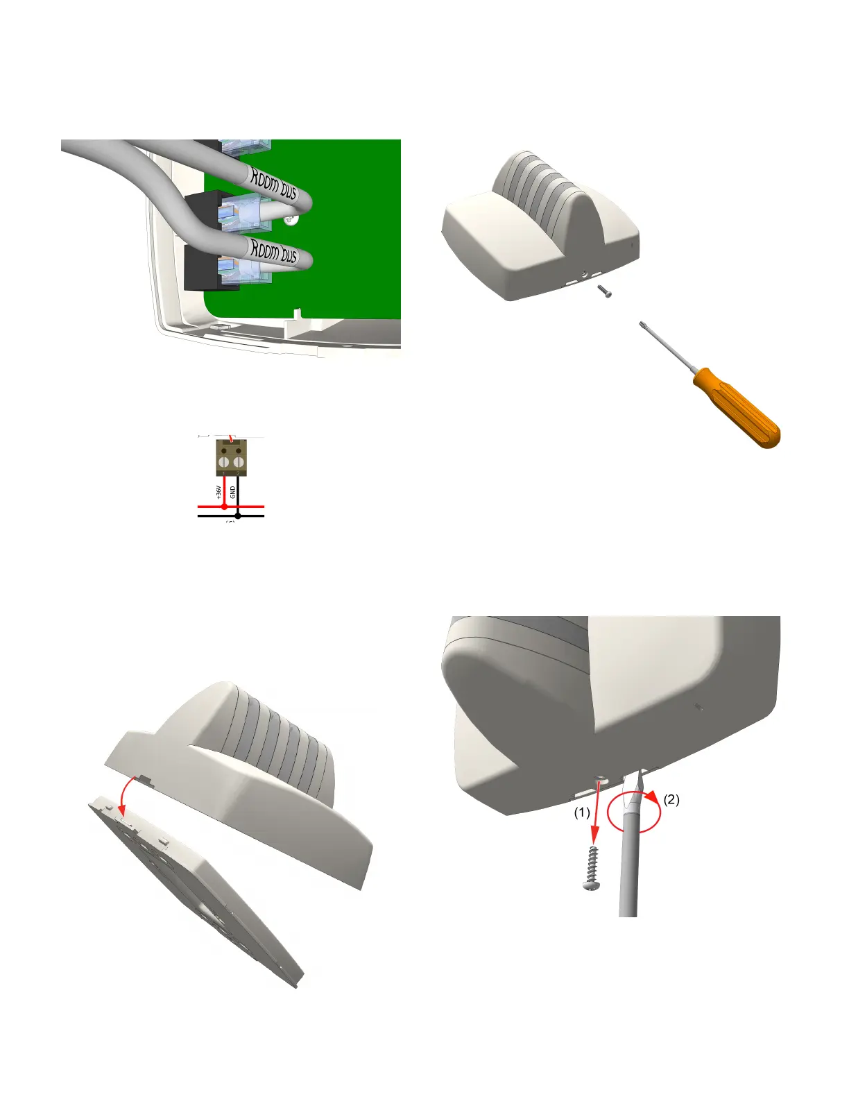
4. Insert the RJ-45 connector from the room bus cable into
an RJ-45 jack on the back of the dome light. If you are
cabling a second room bus, insert the other RJ-45 cable
connector into the open room bus jack. Note that both
room bus jacks share a common data line; however, each
jack can supply a 500mA current (maximum) for the line.
5. Using a 2-pole screw-type block connector (sold
separately), connect the positive wire from the hallway
bus to +36VDC on the dome light’s header pin. Connect
the negative wire to GND.
6. Mount the block connector to the 2-pole terminal on the
NUDL’s power terminal. See Figure 2, item 5.
To mount the dome light to the backplate:
1. Ensure that all cable connections are properly secured to
the jacks and terminals on the back of the dome light.
2. Place the dome light onto the two top fasteners of the
backplate.
3. Press the dome light firmly against the backplate so that
the dome light’s bottom fasteners snap closed on the
backplate.
4. Insert the locking screw into the bottom of the dome
light, and then tighten the screw until it is snug, as
shown below. Do not over tighten.
Removal
Follow the steps below to remove NUDL-series dome lights
from the backplate.
Caution: Failure to follow the proper removal
procedure may result in damage to the dome light.
1. Remove the locking screw from the bottom of the dome
light.
2. Insert a 6mm flat-blade screwdriver into the notch at the
bottom of the dome light, and then apply light upward
pressure.
 Loading...