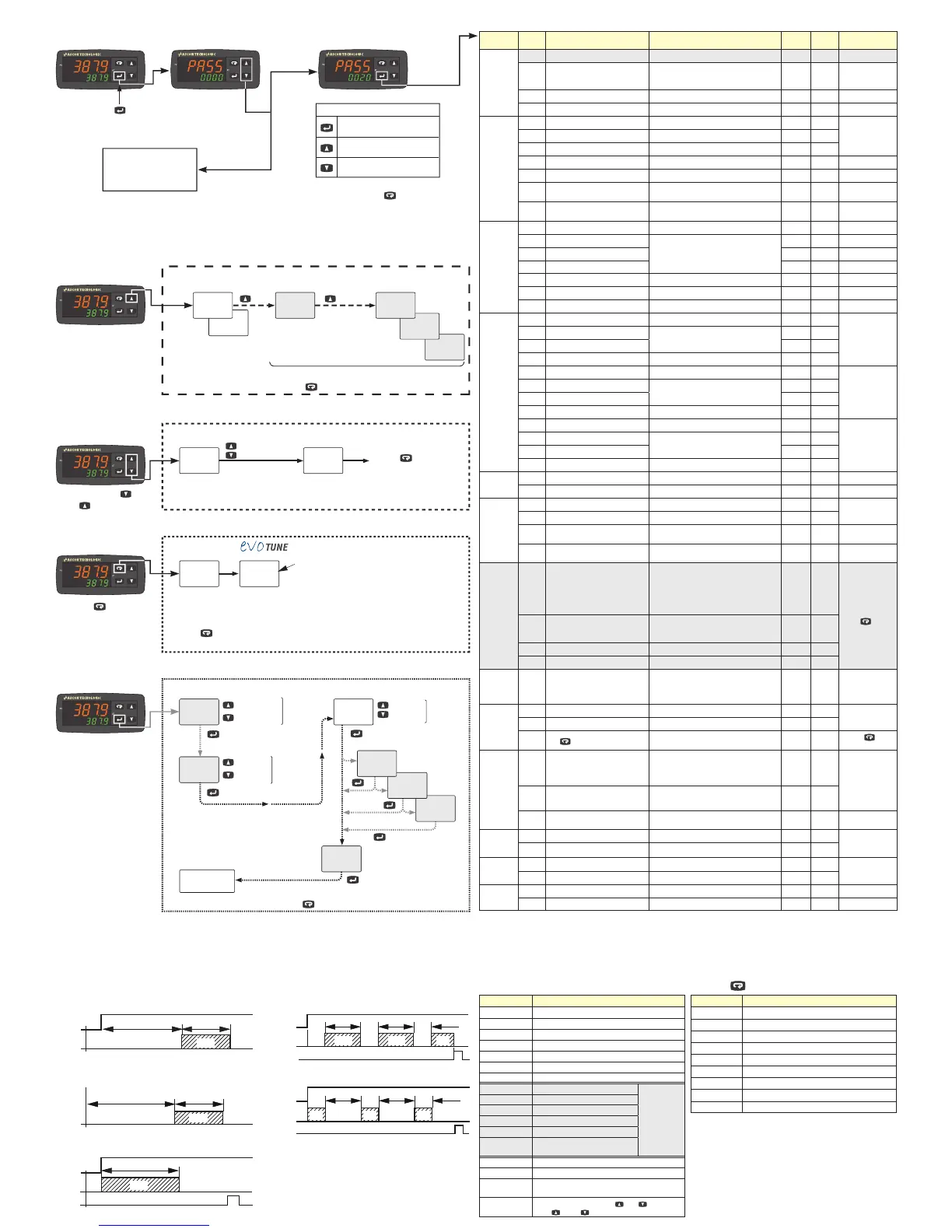
Increase the displayed value
or select the next element
Confirm and go to
Next parameter
Decrease the displayed value
or select the previous element
To exit the parameter setting
procedure press the key (for 3 s)
or wait until the timeout expiration
(about 30 seconds).
Parameters setting
h854
248.0
C045
248.0
sp4
CONTROLLER OPERATION
Increase value
Decrease value
Set Point Change
Operative
Set Point
Changed
operative
Set Point
248.0
sp
250.0
sp
run
tr.st
248.0
sp
nsp > 1
nsp > 2
nsp > 3
Operator Command
run: Start
hold: Hold
res: Reset
Active
Set Point
selection
1
a.sp
If more than
1 Set Point
active
(nsp > 1)
1
st
SP
value
change
340.0
225.0
sp3
If timer
activated
( tr.F )
120.0
sp2
250
AL1
If AL1 is active
Back to the
first parameter
Press the key (3 s) or
wait
for the 10s time out to
store the new Set Point
and return to Normal Mode
Start
Auto-tune
started
Auto-tune
in progress
tunE
248.0
248.0
248.0.
Note:
The key could be assigned by the user to other
functions using the Usrb parameter setting
Dot flashes
while the
Auto-tune
is in progress
To return to the Normal Mode, press the key for 3 seconds or wait for the 10s timeout
Additional Information
Output Value %
(e.g. heating = 35%,
cooling = 45%)
Timer
remaining
time
If active
To return to the Normal Mode, press the key for 3 seconds or wait for the 10s timeout
H035
248.0
t04.8
248.0
d854
248.0
U854
248.0
EVOTUNE
is a fast and fully automatic proce-
dure that can be started in any
condition, regardless the deviation
from SP.
The controller selects automatically
the best tune method and computes
the optimum PID parameters.
Heating
Cooling
Worked time (days)
Worked time (hours)
Power (kW)
or
Energy (Wh)
Depending on
Cod2 digit S setting
Confirm/Next
Confirm/Next
Confirm/Next
Confirm/Next
Confirm/Next
Increase
Decrease
Press the key for 3 seconds
Press and release or
press for more than 2 s
dif$ Digital Inputs DI1 and DI2 Functions
Code displayed Description
0
Disabled (OFF) (default)
1
Alarm Reset
2
Alarm Acknowledge (ACK)
3
Hold of the measured value
4
Stand by mode
5
Manual Mode
6
Heat with “SP” and CooL with “SP2”
7
Timer Run/Hold/Reset [on transition]
Available only
if timer option
and tr.F is
NOT set to
nonE
8
Timer Run [on transition]
9
Timer Reset [on transition]
10
Timer Run/Hold
11
Timer Run/Reset
12
Timer Run/Reset with lock at the
end of the time count
18
Sequential Set Point selection [on transition]
19
SP/SP2 selection
20
Binary coding for Set Point selection on
DI1 and DI2 (00 = SP, 01 = SP2, 10 = SP3, 11 = SP4)
21
Digital inputs in parallel to and keys
(DI1 = , DI2 = )
usrb Key Function
Code displayed Description
nonE
Not used
tune
Starts auto tuning functions (default)
oplo
Manual mode
aac
Alarm Reset
asi
Alarm Acknowledge
chsp
Circular Set Point Selection (shows SP, SP2, SP3)
st.by
Stand-by mode
str.t
Starts/Stop/Reset timer
HE.co
Heat with “SP”/CooL with “SP2”
i.d.a Delayed ON at Start command
Timer Types (selected by tr.f) (option)
i.up.d Delayed ON at Power ON
i.d.d
At Start command
i.p.l
Asymmetrical oscillator with start in OFF
i.L.p Asymmetrical oscillator with start in ON
Start
OUT
ON
off
Tr.t1 Tr.t2
off
OUT
PWR ON
ON
off
Tr.t1 Tr.t2
off
Start
OUT
Reset
ON
Tr.t1
off
Start
OUT
Reset
ONoff
Tr.t2
ONoff
Tr.t1Tr.t1
Tr.t2
ON
off
Tr.t1
Tr.t2
Start
OUT
Reset
ON off
Tr.t2
off
Tr.t1Tr.t1
Tr.t2
off
Tr.t1
Tr.t2
ON ON
PWR ON
Parameters List (PASS: 20) (in gray the parameters related to optional features)
Group Param. Description Range value or selection list elements Default
User
value
Note
Commands
tr.St
Timer status Option
oPEr
Operative Mode Selection
reg Auto,
oplo Manual,
stdy Standby
a.sp
Set Point Selection 0 = SP, 1 = SP2, 2 = SP3, 3 = SP4 0
tune
Start Auto Tune 0 = oFF, 1 = start 0 evoTUNE
Control
Pb
Proportional Band 1... 9999 (Engineering Units = E.U.) 20
Cod1 Digit N = 1
ti
Integral Time 0... 10000 s 200
td
Derivative Time 0... 1000 s 50
HSEt
Hysteresis ON/OFF Control 0... 9999 (E.U.) 1
Cod1 Digit N = 0
tc.H
Heating output cycle time 0.2... 130 s 20.0
Cod1 Digit N = 1
rcg
Relative Cooling Gain 0.01... 99.99 1.00
Cod1 Digit N = 1
Cod1 Digit O > 4
tcc
Cooling output cycle time 0.2... 130 s 20.0
Cod1 Digit N = 1
Cod1 Digit O > 1
Set Point
SP
Set Point 1 -1999... +9999 (E.U.)
SP2
Set Point 2
-1999... +9999 (E.U.)
If nSP
> 1
SP3
Set Point 3
If nSP
> 2
SP4
Set Point 4
If nSP
> 3
SPLL
Set Point min. Value -1999... SPHL (E.U.)
SPHL
Set Point max. Value SPLL... 9999 (E.U.)
nSP
No. of Set Points 1... 4 1
Alarms
AL1
Alarm 1 threshold AL1L... AL1H
If digit P of
Cod2 is > 1
al1l
Alarm 1 low threshold/Low limit
-1999... +9999 (E.U.)
-1999
al1H
Alarm 1 high threshold/High limit 9999
HAL1
AL1 hysteresis 1... 9999 (E.U.) 1
AL2
Alarm 2 threshold AL2L... AL2H
If digit Q of
Cod2 is > 1
al2l
Alarm 2 low threshold/Low limit
-1999... +9999 (E.U.)
-1999
al2H
Alarm 2 high threshold/High limit 9999
HAL2
AL2 hysteresis 1... 9999 (E.U.) 1
AL3
Alarm 3 threshold AL3L... AL3H
If digit R of
Cod2 is > 1
al3l
Alarm 3 low threshold/Low limit
-1999... +9999 (E.U.)
-1999
al3H
Alarm 3 high threshold/High limit 9999
HAL3
AL3 hysteresis 1... 9999 (E.U.) 1
Soft Start
stp
Soft Start Output value -100... 100% 0
Sst
Soft Start Time 0.00... 8.00 (hh.mm) 0
Input
ssc
Low Scale readout -1999... 9999 -1999
For linear Input
types only
fsc
High Scale readout -1999... 9999 9999
dP
Number of decimals
0... 3 (linear inputs),
0... 1 (other inputs)
0
FiL
Measured value Digital filter
0 OFF,
0.1... 20.0 s
0
Timer
tr.F
Timer Type
nonE Timer not used,
i.d.A Delayed ON at start command,
i.uP.d Activation ON at Power ON,
i.d.d At start command,
i.P.L Asymmetrical oscillator, start in OFF,
i.L.P Asymmetrical oscillator, start in ON
none
Timer manage-
ment (Start, Stop,
Reset) can be
done using the
tr.St command
or the
key
(if programmed)
or by the DI1/DI2
digital inputs (if
programmed).
tr.u
Timer Units
0 hh.mm,
1 mm.ss,
2 sss.d
1
tr.t1
Time 1 00.01... 995.9 1.00
tr.t2
Time 2 00.00... 995.9 1.00
I/O
io4.F
I/O 4 Function
ON Transmitter
Power Supply,
OUT4 SSR out,
Di2C Digital Input from contact,
Di2U 24 VDC Digital Input
ON
Digital
Inputs
diF.1
Digital Input 1 Function
0... 21 0
See the DI1, DI2
functions table
diF.2
Digital Input 2 Function
0... 21 0
usrb
Key
Function
nonE, tunE, oplo, aac, asi, chsp,
st.by, str.t, HE.co
tunE
See the Key
function table
Display
di.cl
Colour of the Process Value
display
0 Change,
1 Red,
2 Green,
3 Orange
2
If Change, the
colour is green if
PV differs from SP
less than Ade, red
if higher than Ade
and orange if is
lower than Ade
ade
Display change color threshold
(when di.Cl = 0)
0 OFF
1... 9999 (E.U.)
dis.t
Display Power OFF time
0 Display ON
0.1... 99.59 (mm.ss)
oFF
Serial
communi-
cations
Add
Instrument Address 1... 254 1
Modbus RTU slave
protocol
bAud
Baud rate 1200, 2400, 9600 baud, 19.2, 38.4 kbaud 9600
Wattmeter
Uolt
Load Voltage 1... 999 (V) 230
If digit S of
Cod2 is > 1
cur
Load Current 1... 9999 (A)
Password
PAS4
Configuration access Password 0... 999 300
PAS2
Parameters access Password 0... 999 20
Note: To access all the instrument features, please see the “Complete configuration procedure” in the “Engineering Manual”.
Complete Configuration and Parameter setting can be easily uploaded from the controller and downloaded to other controllers using the:
Configuration Key and Communication Adapter model: A-01.
 Loading...