Ascon Tecnologic - e34B - OPERATING INSTRUCTIONS - PAG. 1
e34B
DIGITAL ELECTRONIC
TEMPERATURE CONTROLLER
WITH DEFROSTING FUNCTION
OPERATING INSTRUCTIONS
20/06 - code: ISTR_M_e34B_E_02_--
ASCON TECNOLOGIC S.r.l.
Viale Indipendenza 56, 27029 - VIGEVANO (PV) ITALY
Tel.: +39 0381 69871 - Fax: +39 0381 698730
http:\\www.ascontecnologic.com
info@ascontecnologic.com
PREFACE
This manual contains the information necessary for
the product to be installed correctly and also instruc-
tions for its maintenance and use; we therefore recom-
mend that the utmost attention is paid to the following
instructions and to save it.
This document is the exclusive property of Ascon Tecnologic
S.r.l. which forbids any reproduction and divulgation, even
partially, of the document, unless expressly authorized.
Ascon Tecnologic
S.r.l. reserves the right to make any formal
or functional changes at any moment and without any notice.
Ascon Tecnologic S.r.l. and its legal representatives do not
assume any responsibility for any damage to people, things
or animals deriving from violation, wrong or improper use or
in any case not in compliance with the instrument features.
Whenever a failure or a malfunction of the device
may cause dangerous situations for persons, thing
or animals, please remember that the plant has to be
equipped with additional electromechanical devices
which will guarantee safety.
1. INSTRUMENT DESCRIPTION
1.1 General description
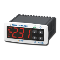
The model e34B is a microprocessor based digital electronic
temperature controller that is typically used in cooling applica-
tions with ON/OFF temperature control and defrost control
at time intervals, by arrival at temperature or by length of time
of continuous compressor operation through stopping the
compressor, electric heating or hot gas/cycle inversion.
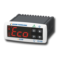
The controller is equipped with special defrost optimization
functions and with other functions that can be used to obtain
energy savings from the controlled system.
The instrument has up to 4 relay outputs and up to 3 NTC
temperature probes inputs one of which can be config-
ured as digital input.
The instrument has an internal buzzer for the acoustic
alarms signalling and a voltage alarm system that deacti-
vates the outputs if the mains voltage is too high/low.
Index
1. Instrument description ............................................... 1
1.1 General description ........................................................... 1
1.2 Front panel pescription ..................................................... 2
2. Programming ............................................................... 2
2.1 Fast Normal Set Point Programming.................................2
2.2 Standard mode parameters programming ........................ 3
2.3 Parameter protection using a Password ........................... 3
2.4 Customized mode parameter programming
(parameters programming level) .......................................3
2.5 Reset parameters to default value .................................... 4
2.6 Keyboard lock function ......................................................4
2.7 Variables display ............................................................... 4
3. Usage warnings ........................................................... 4
3.1 Admitted use ..................................................................... 4
4. Installation warnings ................................................... 5
4.1 Mechanical mounting ........................................................ 5
4.2 Dimensions [mm] .............................................................. 5
4.3 Electrical connections ....................................................... 5
5. Functions ..................................................................... 6
5.1 ON/Stand-by function ........................................................6
5.2 Normal, Economic and Turbo operation ............................ 6
5.3 Measure and display configuration ................................... 7
5.4 Digital input configuration .................................................. 7
5.5 Outputs and buzzer configuration ..................................... 7
5.6 Temperature control .......................................................... 8
5.7 Compressor protection function and power-on delay ........ 9
5.8 Defrost control ................................................................... 9
5.9 Evaporator fans control ................................................... 11
5.10 Alarm functions ............................................................... 12
5.11 Function of keys / and / ................................... 13
6. Accessories ............................................................... 13
6.1 Parameters configuration by A01 ....................................13
6.2 Parameters configuration by AFC1 ................................. 14
6.3 Remote display “TVR Y” .................................................. 14
6.4 RS485 Serial Interface with ARS1 .................................. 14
7. Programmable parameters table .............................. 15
8. Problems, maintenance ............................................ 18
8.1 Notifications .................................................................... 18
8.2 Cleaning .......................................................................... 18
8.3 Disposal .......................................................................... 18
9. Warranty and Repairs ............................................... 18
10. Technical data ............................................................ 18
10.1 Electrical characteristics ................................................. 18
10.2 Mechanical characteristics .............................................. 18
10.3 Functional features ......................................................... 19
11. Instrument ordering code ......................................... 19