Ascon Tecnologic - e34B - OPERATING INSTRUCTIONS - PAG. 13
5.10.2 External alarm from digital input
The instrument can signal an alarm external to the instrument
using the digital input setting iFi = 4 or 5. The instrument
signals the alarm turning ON the
alarm LED ( )
and display-
ing AL label alternated to the variable set with parameter Ids.
Mode iFi = 4 operates no action on the control output, while
iFi = 5 deactivates the control output at digital input intervention.
5.10.3 Open door alarm
The instrument can signal the open door alarm coondition using
the digital input setting iFi = 1, 2 and 3. As the digital input is
activated, the instrument signals that the door is open showing
on the display the oP label alternated to the variable set with
parameter ids.
After the delay set with parameter AoA the instrument signals
the Open Door alarm with the configured devices (buzzer and/
or Output), lighting up the LED while showing the oP label.
At the open door alarm intervention are also re-activated the
inhibited outputs (compressor).
5.10.4 Mains voltage alarms
The instrument can automatically disable the control outputs
when the mains voltage, measured by the instrument through
its power supply, is lower or higher than the values set at
parameters:
ULU Low voltage alarm (expressed as V x 10);
UHU High voltage alarm (expressed as V x 10).
When the alarm triggers and after the delay programmed to
the UUd parameter, the instrument disables the control out-
puts, signals the alarm by activating the configured device
(output and/or buzzer) and shows HU (high voltage alarm), or
LU (low voltage alarm) on the display alternated to the vari-
able set with dS parameter.
If the voltage measurement is not correct, it can be changed
with an offset that can be set using the UOU parameter.
UHU
e.g. 250 V
ULU
e.g. 200 V
offoffoff
ON ON
HU LU
AL
10 V
10 V
Volt
time
V
5.11 Function of keys / and /
The / key function can be defined using the tUF param-
eter to perform the following functions:
oF The key carries out no function;
1 Pressing the key for at least 1 s, is possible to enable/
disable the ECO operating mode. Once the selection has
been made, the display shows for about 1 s the active Set
Point code (SP1, SP2, SP3 or Eco) and its value. When
the instrument exits the ECO operating mode, it returns at
the same operating mode it was using at ECO enabling;
2 Pressing the key for at least 1 s is possible to switch the
instrument from ON to Stand-by state and vice-versa.
The / key function can be defined using the tFb param-
eter to perform the following functions:
oF The key carries out no function;
1 Pressing the key for at least 1 s, is possible to enable/dis-
able the L1 light output or the auxiliary output, if config-
ured as oFo = 2.
6. ACCESSORIES
The instrument is equipped with a TTL serial communications
port wit a 5 poles connector that allows to connect some ac-
cessories described in the following paragraphs.
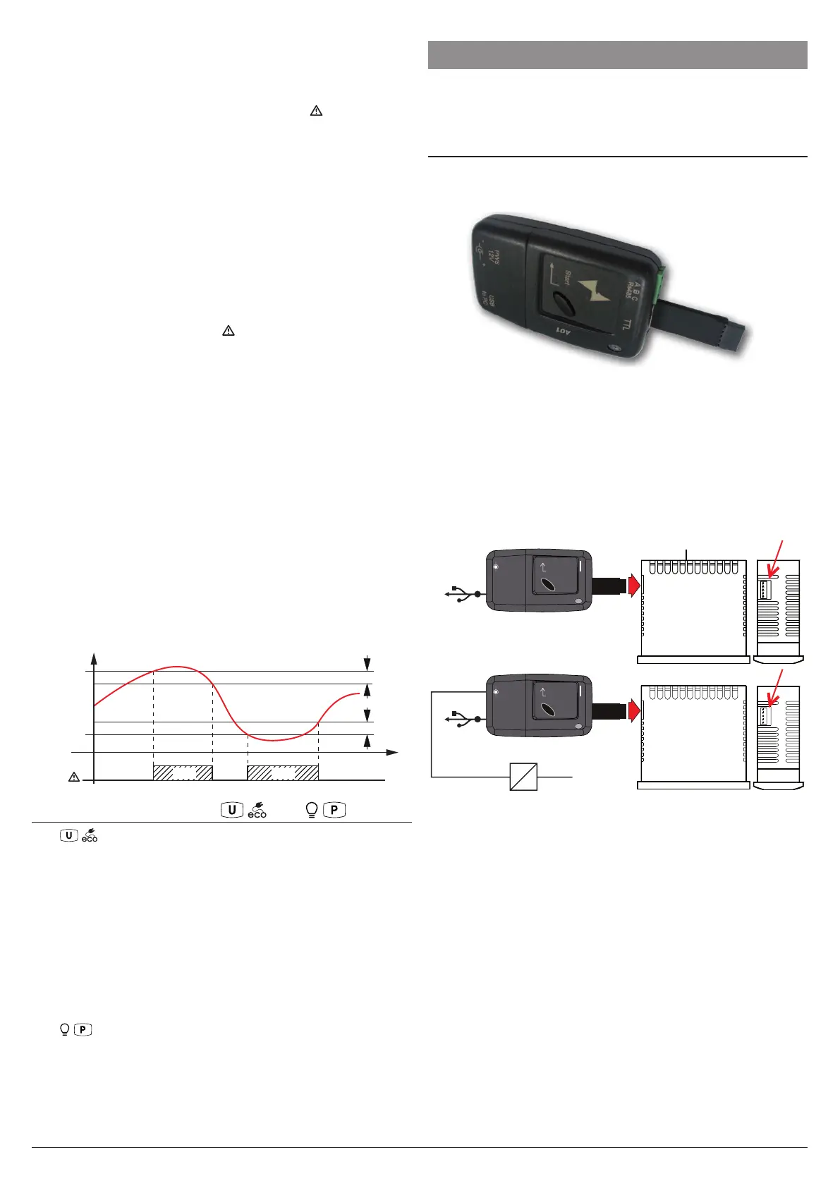
6.1 Parameters configuration by A01
Through the TTL port and with the A01 device, is possible
to transfer from and toward the instrument all the functioning
parameters.
The A01 is mainly usable for the serial programming of some
instruments which need to have the same parameters con-
figuration or to keep a copy of the parameters settings of an
instrument and allow its rapid retransmission.
The same device allows to connect a PC via USB with which,
through the appropriate configuration software for “AT Univer-
salConf tools”, the operating parameters can be configured.
To use the device A01 it is necessary that the device or instru-
ment are being supplied directly or through the key.
AC supply
Supply adapter
12 VDC
Power supply
Enter
PWS
12 V
A B C
TTL
+-
USB
to PC
USB
Enter
PWS
12 V
A B C
TTL
+-
USB
to PC
USB
For additional info, please have a look at the A01 instruction
manual.