Ascon Tecnologic - e34B - OPERATING INSTRUCTIONS - PAG. 2
The 4 outputs can be used to control the compressor or the
temperature control device, the defroster, the evaporator
fans and a configurable auxiliary device (Light, Alarm, etc.).
The 3 inputs for temperature probes can be used for the
cell temperature control, to measure the evaporator tem-
perature and/or other auxiliary temperatures (e.g. products
temperature, condenser temperature, etc.).
The digital input, alternative to the Pr3 probe, can be config-
ured to perform various functions such as: cell gate signal,
defrost commands, selection of a different set of temperature
control, signaling of an external alarm, activation of a continu-
ous cycle, activation of the auxiliary output etc..
The operating parameters configuration can be made through
the keypad, through the A01 device connected to the TTL
port (standard) or using the NFC communication (optional).
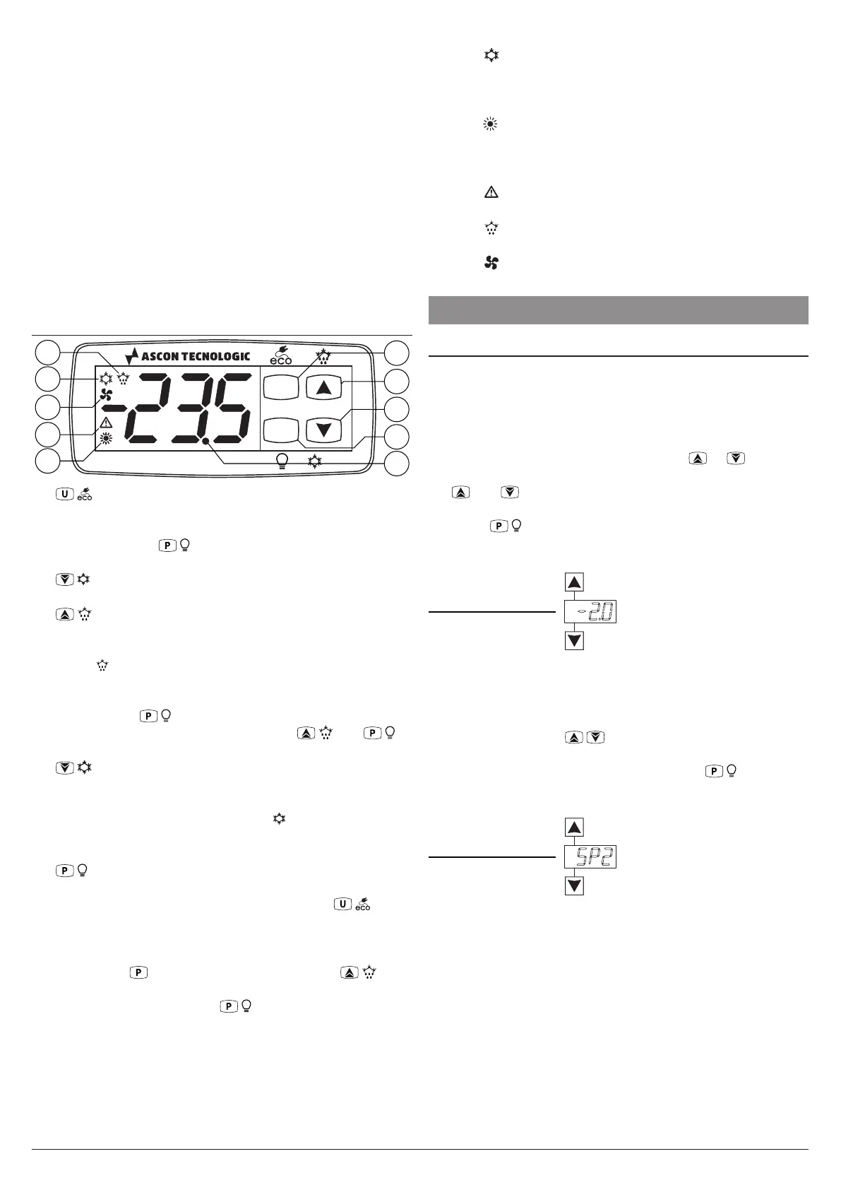
1.2 Front panel pescription
e34B
P
U
trb
4
2
1
5
9
7
8
10
6
3
1 / : Pressed for about 1 s enables the ECO function
or turns the instrument ON/OFF (Stand-by). The function
selection is made with tUf parameter. Pressed for 5 s
together with the / key, allows to access to the param-
eter programming mode. Pressed for 5 s together with the
/ key allows to access the variable display mode. In
programming mode it is used to return to normal operation;
2 / : In normal mode, pressed an released allows to
access the direct Set Point selection/change modality.
Pressed for 5 s can be used to start/stop manual defrost
cycle ( ). In programming mode and in variable display
mode is used to select the parameters and to increase
the value to be set. In programming mode can be used
together with /
key to change parameters level.
When the keyboard is locked, the keys / and /
used together (hold pressed for 5 s), unlock the keyboard.
3 /
turbo:
In normal mode, pressed an released al-
lows to access the direct Set Point selection/change
modality. Pressed for 5 s can be used to start/stop a
control cycle with “turbo” modality ( ). In programming
mode and in variable display mode is used to select the
parameters and to increase the value to be set.
4 / : Pressed for about 1 s enables/disables the output
selected as “Light”. The function selection is made with tfb
parameter. Pressed for 5 s together with the / key,
allows to access to the parameter programming mode.
In programming mode is used to enter in parameters
edit mode and confirm the entered values. In program-
ming mode can be used together with the / key
to change the programming level of the parameters.
Pressed together with the /
key for 5 s allows the
keyboard unlock.
5 LED dp/Stand-by: During the normal operation is the
decimal point, when the instrument is placed in Stand-
by mode, this is the only lighted LED. In programming
mode, while the parameter code is displayed, the dot
indicates the parameter protection level: not protected
(lit up), protected (flashing) and hidden (turned OFF).
6 LED
: Indicates the output status (compressor or
temperature control device) when the instrument
is programmed for cooling operation; ON (lit up),
OFF (turned OFF) or inhibited (flashing).
7 LED : Indicates the output status (compressor or temper-
ature control device) when the instrument is programmed
for heating operation; ON (lit), OFF (turned OFF) or inhib-
ited (flashing).
8 LED
: Indicates the alarm status: ON (lit),
OFF (turned OFF) or silenced or stored (flashing).
9 LED : Indicates that the defrost is in progress (on) or
drainage time in progress (flashing).
10 LED : Indicates fan output status ON (on), OFF (off)
or inhibited (flashing).
2. PROGRAMMING
2.1 Fast Normal Set Point Programming
The instrument allows, through the tEd parameter, to man-
age the selection of the regulation Set point according to two
distinct modes.
Setting tEd =1 the instrument allows the SP1 Set Point set-
ting inside the limits inserted with SPH and SPE parameters.
Using this method, press and release the or key, the
controller anwers showing the SP1 active, at this point, using
the and keys is possible to change the SP2 value to
the desired one. Once the desired value has been selected,
press the / key or wait 10 s after which the instrument
makes the new set Point value active and the display returns
to the normal operating mode.
Max. = spE value
ECO SET (e.g. 10°)
Min. = spH value
Turbo SET (e.g. -10°)
Increase
value
Decrease
-2.0
tEd = 1 mode
Set Point programming
Setting tEd = 2, the controller allows to select which of the 3
pre-set Set Points (SP1, SP2, SP3) is to be set to active. In
this mode, pressing and releasing the ss / dd key the instru-
ment shows the active Set Point (SP1, SP2, SP3) alternatedto
its value, pressing the / keys again it will be possible to
select which one of the three is to be activated. Once the de-
sired Set Point has been activated, press the / key or wait
10 s after which the instrument makes the selected Set Point
active and the display returns to the normal operating mode.
sp1 (e.g. 4.0°)
sp2 (e.g. 2.0°)
selection
Decrease
selection
sp2
tEd = 2 mode
Set Point selection
sp3 (e.g. 0.0°)
Note: The use of the device with tEd = 2 is the most practi-
cal and
simple for the end user who, with the opera-
tions illustrated below, can easily select, as the active,
one among the 4/5 preset Set Point temperatures (SPE,
SP1, SP2 , SP3 and SPH).