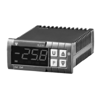
ASCON TECNOLOGIC - TLZ 20
-
OPERATING INSTRUCTIONS - Vr. 02 – ISTR-MTLZ20IEFD02 - PAG. 5
transformer TCTR, or with equivalent features, and to use only one
transformer for each instrument because there is no insulation between supply
and input. We recommend that a check should be made that the parameters
are those desired and that the application functions correctly before
connecting the outputs to the actuators so as to avoid malfunctioning that may
cause irregularities in the plant that could cause damage to people, things or
animals.
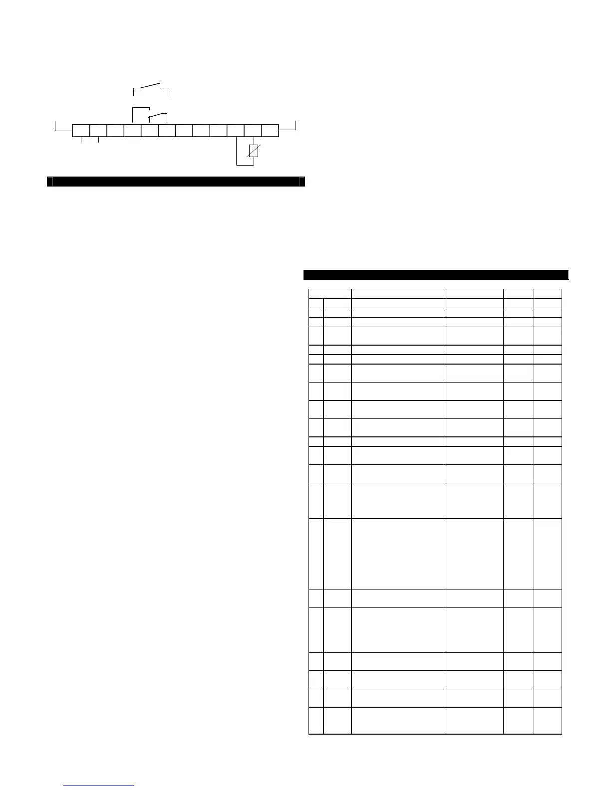
S U P P L Y
P T C -N T C
21
T L Z 2 0
CN CN O
O U T
53 4 76
S P D T 1 6 A -A C 1
N O
C
S P S T -N O 1 6 A - A C 1
IN P U T
1 08 9 1 21 1
P R O B E
4 - FUNCTIONS
4.1 - MEASURING AND VISUALIZATION - Via the parameter “SEnS” it is
possible to select the type of probes that one wishes to use and which can be:
thermistores PTC KTY81-121 (Ptc) or NTC 103AT-2 (ntc). Once the type of
probe used has been selected, through the parameter “Unit”, it is possible to
select the temperature unit of measurement (°C or °F) and, through the
parameter “dP”, the resolution of the desired measurement (OFF=1°; On
=0,1°). The instrument allows the measuring to be calibrated, that can be used
for re-calibrating the instrument according to application needs, through the
parameters “OFS”. Using the parameter “FiL”, it is possible to set the time
constant for the software filter for measuring the input values to be able to
reduce the sensitivity to measurement disturbances (increasing the time).
Please remember that visualisation of the probe can be changed by the
display block in defrosting function too, by using the parameter “dLo” (see
par. 4.4).
4.2 - TEMPERATURE CONTROL - The regulation of the instrument is
ON/OFF and acts on the output “OUT” depending on the measuring of probe,
of the Set Point “SP”, the intervention differential “HSEt” and the function
mode “Func”. Depending on the function mode programmed on the
parameter “Func” the differential is automatically considered by the regulator
with positive values for a Refrigeration control (“Func”=CooL) or with negative
values for a heating control (“Func”=HEAt). In the event of probe error, it is
possible to set the instrument so that that the output “OUT” continues to work
in cycles according to the times programmed in the parameter “tonE”
(activation time) and “toFE” (deactivation time). If an error occurs on the
probe the instrument activates the output for the time “tonE”, then deactivates
it for the time “toFE” and so on whilst the error remains. Programming “tonE” =
OFF lthe output in probe error condition will remain switched off. Programming
instead “tonE” to any value and “toFE” = OFF the output in probe error
condition will remain switched on. Remember that the temperature regulation
function can be conditioned by the “Compressor Protection” function described
below.
4.3 - COMPRESSOR PROTECTION FUNCTION AND DELAY AT POWER-
ON - The function “Compressor Protection” carried out by the machine aims to
avoid close start ups of the compressor controlled by the instrument in cooling
applications. This function foresees a time control on the switching on of the
“OUT” output associated with the temperature regulation request. The
protection consists of preventing the output being switched on during the time
set in the parameter “PtC” and counted depending on what has been
programmed in the parameter “PSC”, and therefore that any activation occurs
only after the “PtC” time has finished. If during the power on delay phase, the
regulator request should disappear, due to an inhibition caused by the
compressor protection function, the foreseen start up of the output is naturally
cancelled. Using the parameter "PSC", it is possible to set the type of
compressor protection and therefore from when the inhibition time “PtC” must
start. The parameter “PSC” can be set as:
= 1 : Power on delay
= 2 : Delay after power off
= 3 : Delay between power on phases.
The function is disabled by programming “PtC” = 0. During the power on delay
phases of the OUT output by inhibiting the function “Compressor Protection”
the led OUT flashes. It is also possible to prevent activation of the output after
the instrument is turned on, for the time set in the parameter “od”. The
function is disabled by “od” = OFF. During the power on delay phase, the
display shows the indication od, alternating with the normal programmed
visualisation.
4.4 - DEFROST CONTROL - The automatic control of defrost, that is by
stopping compressor, occours according to this parameters:
"dCt" : Defrost interval computation
- rt - based on real time (instrument on)
- ct - based only on compressor running time (output on)
"dint" : Interval between defrost cycles
"dEFE" : Lenght of defrost cycles
The instrument switch off the output for the time “dEFE” each “dint” time (of
real time functioning if “dCt” = rt, or of compressor running time if “dCt” = ct).
The occurring defrost cycle is signalized by the led DEF. Through par.
“dLo”,“Etdu” and “dALd” it’s possible to define the display behaviour during
defrost. The “dLo” parameter pemits the display visualization lock on the last
temperature reading (dLo = On) during all the defrost cycle until, at the end of
defrost, the temperature has not reached the value [SP + Etdu] or is ended the
time setted on par. "dALd". Or it permits the visualization of label "dEF" (“dLo”
= Lb) during the defrost cycle and, after the defrost, of label "PdEF" until, at
the end of defrost, the temperature has not reached the value [SP + Etdu] or is
ended the time setted on par. "dALd". The display will otherwise continue to
visualize the temperature measured by the probe during the defrost cycle
(“dLo”= OFF).
4.5 - MANUAL DEFROST - To start up a manual defrosting cycle, press the
key UP/DEFROST when it is not in programming mode and keep it pressed
for about 5 seconds after which, if the conditions are correct, the led DEF will
light up and the instrument will carry out a defrosting cycle.
4.6 - FUNCTIONING OF KEY “U” - The U key function can be defined by the
parameter “USrb” and can be configured for the following functions:
= OFF - The key U carries out no function.
= 1 - Pressing the key for at least 1 second, it is possible to switch the
instrument from the ON status to Stand-by status and vice versa.
4.7 - PARAMETERS CONFIGURATION BY “KEY01” - The instrument is
equipped with a connector that allows the transfer from and toward the
instrument of the functioning parameters through the device TECNOLOGIC
KEY01 with 5 poles connector.
For additional info, please have a look at the KEY01 instruction manual.
5 - PROGRAMMABLE PARAMETERS TABLE
Par. Description Range Def. Note
1
SPLL
Minimum Set Point -58.0 ÷ SPHL -50.0
2
SPHL
 Loading...