10
Power
supply
switch
RS485
C
V
~
[3]
[6]
[6]
[5]
[5]
[5]
OP1
OP2
PTC
Alarm
Supervision
12
11
10
3
2
1
32
31
30
29
28
27
26
25
A
b
B
IN1
PT100
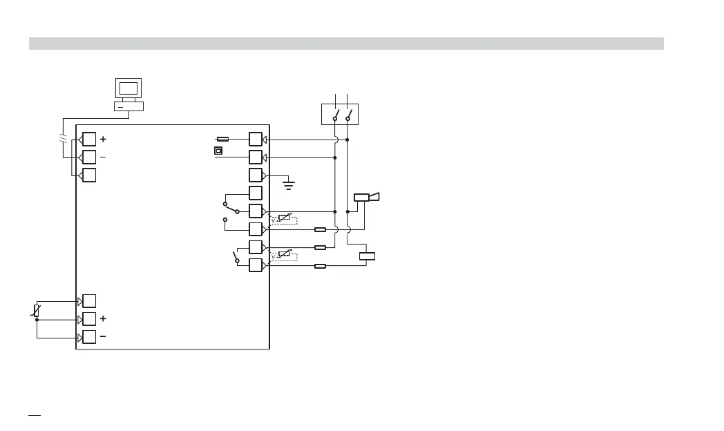
2 - Electrical connections
2.3 EXAMPLE OF WIRING DIAGRAM
B
Notes:
1] Make sure that the power supply voltage is
the same as indicated on the instrument.
2] Switch on the power supply only after all
the electrical connections have been com-
pleted.
3] In accordance with safety regulations, install
a circuit breaker on the instrument power
supply line that is clearly identified with that
instrument (or group of instruments). The
breaker shall be easily accessible by the
operator.
4] The instrument is PTC protected. In case
of failure it is suggested to return the instru-
ment to the manufacturer for repair.
5] To protect the instrument internal circuits
use:
- 2 AT fuse for Relay outputs (220 Vac);
- 4 AT fuse for Relay outputs (110 Vac).
6] Relay contacts are already protected with
varistors.
Only in case of 24 Vac inductive loads,
use model A51-065-30D7 varistors (on
request)
J1 EN-ed3 17-02-2009 15:05 Pagina 10

 Loading...