11
2 - Electrical connections
Wire resistance
150Ω max.
For 3 wires only.
Maximum line
resistance: 20Ω/line
Use wires of the same
length and 1.5 mm
2
size.
Maximum line
resistance: 20Ω/line
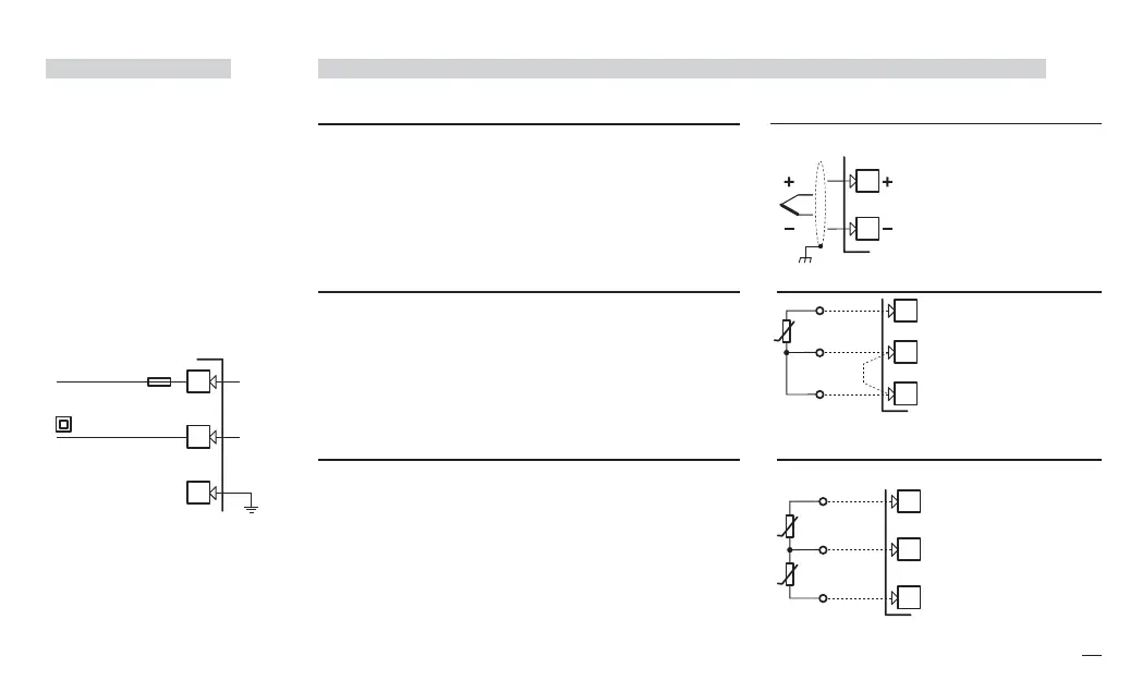
2.3.1 POWER SUPPLY
B
Switching power supply with mul-
tiple isolation and internal PTC
• Standard version:
nominal voltage:
100...240Vac (-15...+10%)
Frequency 50/60Hz
• Low Voltage version:
Nominal voltage:
24Vac (-25...+12%)
Frequency 50/60Hz
or 24Vdc (-15...+25%)
For better protection against
electrical interference, it is rec-
ommended not to connect the
ground clamp provided for civil-
ian installations.
2.3.2 MAIN UNIVERSAL INPUT
B
A L-J-K-S-R-T-B-N-E-W thermocouple type
• Connect the wires with the polarity as shown;
• Always use compensation cable of the correct type
for the thermocouple used;
• The shield, if present, must be connected to a prop-
er ground.
B For Pt100 resistance thermometer
• If a 3 wire system is used, always use cables of the
same diameter (1mm
2
min.) (line 20 Ω/lead maximum
resistance);
• When using a 2 wires system, always use cables of the
same size (1,5mm
2
min.) and put a jumper between ter-
minals 11 and 12.
C For ∆T (2x RTD Pt100) Special
A When the distance between the indicator and the
sensor is 15 m using a cable of 1.5 mm
2
size pro-
duces an error on the measure of 1°C (1°F).
R1 + R2 must be <320Ω
L
N
25
26
Included PTC
Supply
27
J1 EN-ed3 17-02-2009 15:05 Pagina 11
 Loading...