Do you have a question about the ASEA AC50Q-3 and is the answer not in the manual?
ASEA Power Systems certifies product testing and compliance with specifications.
ASEA Power Systems warrants units against defects for 18 months post-purchase or 12 months post-installation.
ASEA Power Systems prohibits product use in life support systems due to potential injury.
Details electrical parameters like input/output voltage, current, frequency, and power.
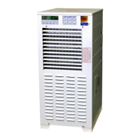
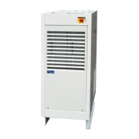
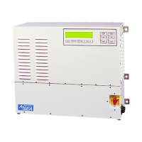
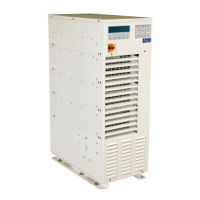
Outlines the physical and environmental characteristics of the converter.
Describes connecting input power using compression terminal blocks for wires 4 AWG to 3/0 AWG.
Details connecting output power using terminal blocks for wires 4 AWG to 3/0 AWG.
Step-by-step guide to turn on the converter, including initialization and display sequence.
Steps to transfer power to generator and shut down the converter without Seamless Transfer.
Procedure to shut down converter after transferring to generator with Seamless Transfer.
Details the RS-232C serial port, pinout, and recommended cabling for communication.
Explains RS-485/Modbus connections, including converter/optical-isolator and master/slave setup.
Overview of software-based resources and features available in shore power converters.
Introduction to the comprehensive Load Management System and its features.
Details operations within the Load Management System, including alarms and setup.
Procedure to access and analyze generator frequency range data.
Explains how to control converter output impedance to manage voltage drops.
Details the Automatic Gain Control feature for compensating output voltage variances.
Describes the kW-hour meter and maximum power level display for monitoring usage.
Allows the user to increase or decrease the converter's output voltage.
Explains how to access and view the converter's event log for monitoring.
Lists common symptoms encountered during operation and their possible causes/solutions.
Details various failure and warning messages displayed by the converter.
Provides information on converter status and reasons for offline operation.
Explains status words used for system diagnostics and monitoring internal logic.
Instructions on recording fault messages and status data before system power down.
Information on software tools for troubleshooting and analyzing converter behavior.
Procedure for checking power module status and disabling a suspected faulty module.
Details the location and rating of power module fuses and safety precautions.
Procedure to calibrate the input (shore power) voltage and current metering system.
Procedure to calibrate the output (converter) voltage and current metering system.
Procedure to calibrate generator voltage metering, applicable with Seamless Transfer Option.
| Brand | ASEA |
|---|---|
| Model | AC50Q-3 |
| Category | Media Converter |
| Language | English |