Version:V1.4 May 8th, 2021
ASENWARE LTD
ADDRESS: 6 PROSPECT WAY, ROYAL OAK INDUSTRIAL ESTATE DAVENTRY,
NORTHAMPTONSHIRE, ENGLAND, NN118PL
WEBSITE: www.asenware.com EMAIL: info@asenware.com
MANUFACTURER: ZHONGSHAN GUTA FIRE EQUIPMENT TECHNOLOGY CO.,LTD
ADDRESS: Xingye Rd, Huoju District Zhongshan City, Guangdong P.R. China
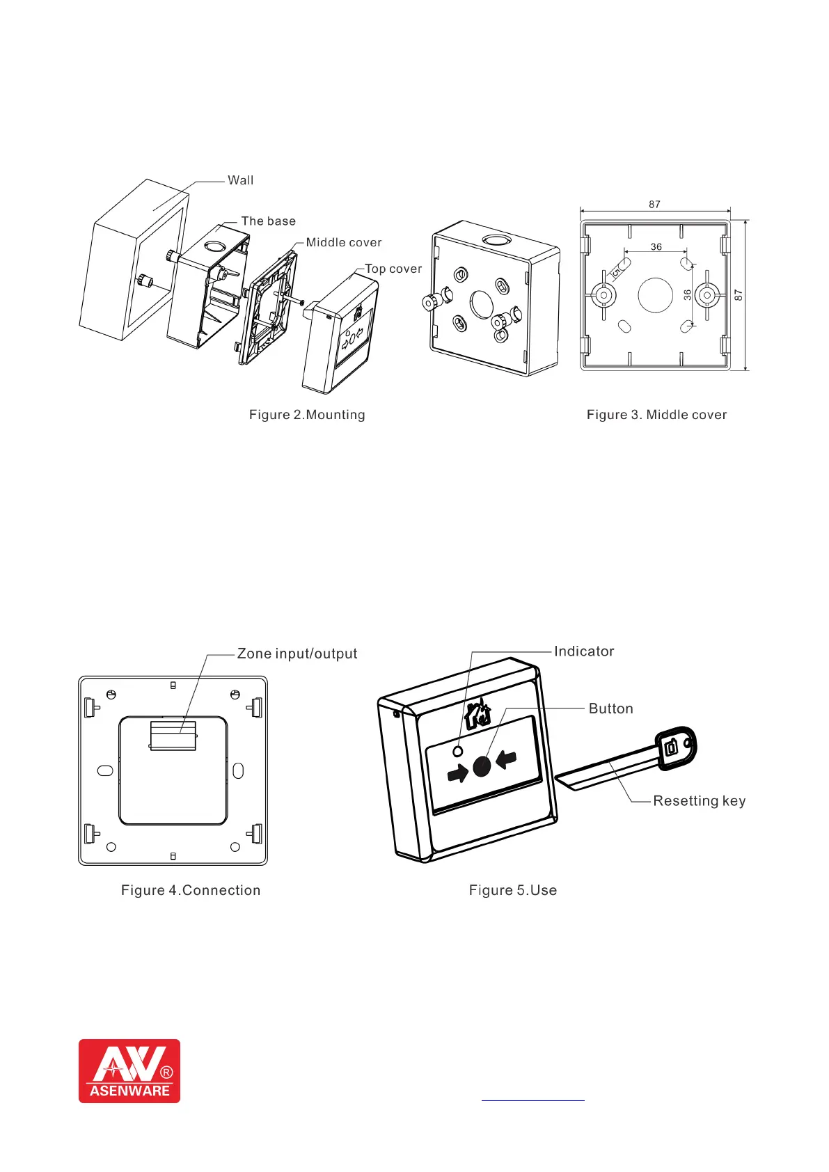
4. Mounting base
Shown in Figure 2, the base is fixed to the wall, fix the middle cover on the base and then fix the top
cover on the middle cover. The base dimensions of 87mm*87mm*33mm(Length*Width*Height),
mounting hole diameter is φ5mm, fixing the hole spacing is shown in Figure 3.
5. Wiring and Connections
According to the wiring diagram, connect the wires to the desired end. Figure 4 shows, it is proper to use
RVS twisted pairs with a section of area of equal to or larger than 0.75mm² for the socket IN or OUT.
6. Use
Start: When there is a fire manual confirmation, press the button on the panel of the AW-D135C(See
Fig.5). After the manual fire alarm is given, the ALARM indicator will remain lit.
Reset: The resetting key into the manual reset button on the side of the hole being depressed can make
restitution by piece, Reset the fire alarm control system and restore the AW-D135C to the normal
monitoring status.
Scan the QR code to watch the wiring video Official website:
www.asenware.com
Technical Support:
www.asenwarefirealarm.com
 Loading...