Do you have a question about the Ashcroft T5500 and is the answer not in the manual?
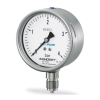
Identifies pressurized parts as a hazard source and stresses gauge selection according to EN 837-2.
Details operator duties for ensuring safe operation, eliminating risks, and adhering to regulations and manual guidelines.
Details area of use (Zone 1, 2, 21, 22) and permitted temperatures for non-switching models.
Specifies area of use (Zone 1, 2) and permitted temperatures for models with inductive proximity switches.
Highlights safety measures, including shut-off valves and securing the plant against accidental restart.
Details process connection, calibration for vertical installation, and connection by qualified staff.
Outlines preconditions for start-up, including proper installation of lines and checking connections.
Stresses depressurizing lines and securing the plant before performing any servicing work.
Warns that defective gauges pose risks to safety and environment, requiring immediate action.
Instructs to take faulty devices out of service and send them for repair, coordinating with the service department.
Lists common fault indicators like pointer issues, leaks, or housing damage, often requiring gauge replacement.
Refers back to the Mounting/Installation chapter (8.3) for procedures following fault rectification.
| Material | Stainless Steel |
|---|---|
| Case Material | 304 Stainless Steel |
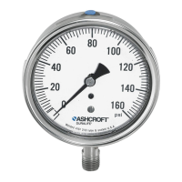
| Type | Pressure Gauge |
| Connection Size | 1/4 NPT |
| Output Signal | None (Mechanical Gauge) |
| Operating Temperature | -20°F to 160°F |
| Wetted Materials | 316 Stainless Steel |
| Temperature Range | -20°F to 160°F |
| Liquid Fill | Glycerin |
| Process Connection | 1/4 NPT |