Do you have a question about the Ashcroft 2074 and is the answer not in the manual?
Lists available units for pressure measurement.
Configures the frequency of pressure readings on the display.
Details options for manual and automatic backlite control.
Defines time intervals for automatic gauge power-off.
Averages readings to stabilize fluctuating process pressure.
Covers zero, span, and mid-scale calibration steps.
Allows disabling specific menu items or keypad functions.
Turns the gauge on and off; initiates startup display.
Resets zero shift and clears min/max values.
Reviews and displays minimum and maximum pressure values.
Finalizes selections and confirms feature choices in menus.
Lists available settings for gauge customization.
Selects the desired unit for pressure measurement.
Accesses and cycles through main menu options for customization.
Manually toggles the backlite on or off.
Establishes a unique password for accessing menu options.
Prompts for password entry to access protected features.
Guides through recalibrating zero, mid, and full-scale.
Restores original factory calibration settings for the gauge.
Sets the tolerance for rezeroing using the Zero/Clear key.
Allows enabling or disabling specific menu functions.
Adjusts the bar graph to represent specific pressure ranges.
Configures the time before the gauge automatically powers off.
Sets the speed at which pressure is updated on the screen.
Averages readings to stabilize minor process fluctuations.
Sets user-defined switch points for output signals.
Sets switch points for rising and falling pressure.
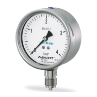
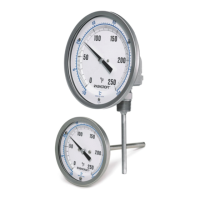
Specifies gauge models, case sizes, and materials.
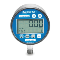
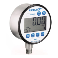
Details display resolution, character height, and bar graph presence.
Overview of keypad actions and menu options.
Describes 4-20mA output, line power, and switching options.
Step-by-step guide for installing loop powered gauges.
Step-by-step guide for installing line powered gauges.
Guide for installing line powered gauges with one switch.
Explains how to connect the single SPDT switch.
Guide for installing line powered gauges with two switches.
Details connections for the first SPDT switch.
Details connections for the second SPDT switch.
Guide for installing combined line/loop powered 4-20mA gauges.
Guide for installing combined wiring with one SPDT switch.
Explains switch connections for the combined unit.
Guide for installing combined wiring with two SPDT switches.
Details connections for the first switch on combined unit.
Details connections for the second switch on combined unit.
| Brand | Ashcroft |
|---|---|
| Model | 2074 |
| Category | Measuring Instruments |
| Language | English |