– 21 –
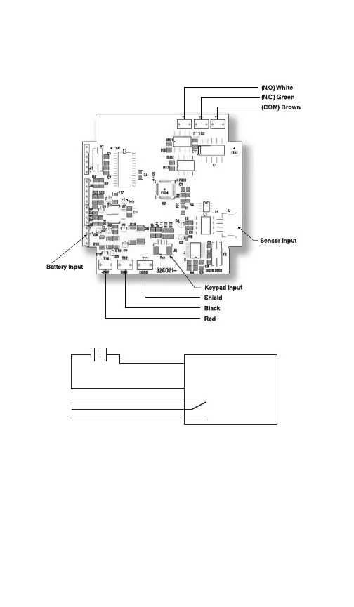
WIRING DIAGRAM
(–exec.) F
(+exec.) E
Line Powered with (1) SPDT switch (Type 2274 XU1)
5 conductor, 22 AWG shielded
Installation Procedure for 2274 XU1:
ESD precautions should be taken. See page 31 for details.
1. Ensure all power is off/disconnected from the circuit.
2. Connect the red wire (E) to the positive power terminal.
3. Connect the black wire (F) to the negative power terminal.
Wiring the Switch:
Normally Open: Use the white and brown wires.
Normally Closed: Use the green and brown wires.
+
POWER
SUPPL Y
(+)
(–)
GAUGE
–
V+
V–
Red (E)
Black (F)
White (NO)
Green (NC)
Brown (Common)
•
I&M008-10109-DIG Rev F 07-12_layout 10/14/13 9:45 AM Page 21

 Loading...