Do you have a question about the ASIRobicon GT3000 and is the answer not in the manual?
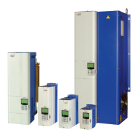
Provides an overview of Variable Frequency Drives (VFDs) and the GT 3000's capabilities.
Explains the converter, DC bus, pre-charge, and inverter circuits of the GT 3000 drive.
Details procedures for inspecting and receiving the drive system upon arrival.
Explains how to identify drive models using nameplate information and part numbers.
Lists the technical specifications, requirements, and limitations for the GT 3000 VFD.
Outlines essential safety measures and warnings for working with GT 3000 drives.
Describes the various AC and DC input voltages and power sources used by the GT3000.
Specifies requirements for test equipment used for verification and safety checks.
Details steps for verifying power removal and capacitor discharge before maintenance.
Explains the mandatory lock-out/tag-out procedures for electrical safety.
Provides safety precautions when working on equipment with input contactors.
Highlights safety considerations when working on output contactors and bypass circuits.
Covers operational safety, internal fuses, and ESD precautions for the drive.
Guidelines for qualified electricians on electrical hook-ups and code adherence.
Instructions on routing conduit and protecting the chassis during installation.
Specifies requirements for running and isolating power and control wiring.
Details on power cable preparation, megger testing, and wire sizing.
Guidance on control wiring practices, checking nameplates, and using shielded cable.
Refers to Appendix A for power terminal block sizing information.
Information on the necessity of input fuses for drive protection.
Explains the use of auxiliary power supplies for blowers and contactors.
Introduces the two methods of user interface: keypads and the PC Tool.
Details the functions of basic, intermediate, and advanced keypad key combinations.
Describes the PC Tool software for programming and monitoring the drive.
Provides step-by-step examples for programming the drive using the keypad.
Guides on verifying installation completeness and performing initial setup.
Describes the available motor control algorithms: V/Hz, Sensorless Vector, and FOC.
Discusses selecting the appropriate standard (EU or NEMA) for VFD programming.
Introduces the two available Microprocessor Boards: Basic and Plus.
Outlines the steps for performing a quick start-up of the motor with the drive.
Details the procedures for initial motor start-up and operation.
Explains the steps required to start and run the drive in automatic operation mode.
Lists and describes the parameters available for Level 2 programming.
Covers the main setting for the Motor Menu, including factory reset.
Explains the Energy Saver function and motor data settings.
Details the V/Hz voltage boost and shutoff settings.
Describes the configuration of digital outputs based on microprocessor type.
Explains the configuration and use of Analog Inputs AI1 and AI2.
Details the configuration and availability of analog outputs.
Introduces various functions for process requirements like Critical Speed En.
Explains how to avoid continuous operation at specific motor frequencies.
Describes limiting motor current during acceleration to prevent overcurrent trips.
Explains limiting DC bus voltage during deceleration without braking devices.
Details the Flying restart function for SLS/FOC modes.
Covers changing speed reference using discrete increments or decrements.
Explains avoiding UnderVolt trips by recovering DC bus energy during power dips.
Describes how the function promptly switches off firing pulses on a stop command.
Explains selecting manual/automatic modes and managing start/stop commands.
Details automatic trip resets and drive restarts, including sequential fault recovery.
Explains how the drive starts/stops based on speed reference thresholds.
Covers managing loss of one phase of the incoming line.
Describes implementing closed loop control for variables like temperature.
Covers setting speed references, limits, and acceleration/deceleration times.
Explains setting the rate of frequency change via deceleration and acceleration ramps.
Details defining upper speed limits acting as clamps for forward and reverse references.
Explains setting acceleration, deceleration times, and jerk rate for ramp profiles.
Defines overload current levels and actions for motor thermal protection.
Configures alarm settings, including response to signal loss.
Enables detection of under-load conditions, typically for pumps.
Describes the function that automatically restores locks and restarts the drive.
Explains how the keypad displays drive status and monitor variables.
Lists and describes common alarm codes and their meanings.
Lists and describes common fault codes and their troubleshooting steps.
Emphasizes following safety shutdown and verification procedures before maintenance.
Outlines a schedule for regular checks to maintain drive performance.
Provides a detailed checklist for physical, visual, and system operation checks.
Introduces system options like circuit breakers, fuses, and contactors for the GT3000.
Details various available options such as enclosures, input devices, fuses, and magnetics.
Provides electrical data for various drive models and configurations.
Details enclosure sizing recommendations for cooling based on drive model.
Specifies power cable and fuse sizing for specific voltage ranges.
Specifies power cable and fuse sizing for higher voltage ranges.
Lists auxiliary supply details for different inverter types.
Provides part numbers for line reactors, RFI filters, and output reactors.
Lists braking unit specifications for drives in the 380-480V range.
Lists braking unit specifications for drives in the 525-690V range.
Shows overall dimensions and weights for drive sizes I through IIIL.
Displays overall dimensions and weights for drive sizes IV through VIL.
Illustrates overall dimensions and weights for drive sizes VII, VIII, and coupled configurations.
Lists GT 3000 6-Pulse options with 400V and 460V ratings.
Details GT 3000 18-Pulse Clean Power options for 400V and 460V.
Lists GT 3000 6-Pulse options for 575V ratings.
Diagram showing GT 3000 drive options for 1-30HP models.
Diagram illustrating GT 3000 drive options for 40-60HP models.
Schematic of GT 3000 drive options for 60HP, 6 Pulse models.
Diagram showing the layout and components of the Microprocessor Basic Board.
Lists jumper and switch settings for the Microprocessor Basic Board.
Diagram illustrating the Microprocessor Plus Control Terminal Board.
Details jumper and switch configurations for the Microprocessor Plus Board.
| Brand | ASIRobicon |
|---|---|
| Model | GT3000 |
| Category | DC Drives |
| Language | English |