2 3
At Signal Distribution
1. Choose a suitable location in the Concourse cabinet to install the HS-V M1100. The
recommended location is near the video combiner, e.g. HS-V H400. This installation
will require optional mounting bracket HS-MOD001 BRKT (not supplied) and small
mounting plate HS-MP200 (not supplied).
2. Home run video and audio patch cords from the source to the HS-VM1100. Note:
The supplied cords may not be long enough for some installations.
3. Connect the RF (video) output patch cord from the video source to the HS-VM1100
“VIDEO IN” jack. See Figure B.
4. (Optional) Connect the audio output patch cord from the source to the HS-VM1100
“AUDIO IN” (3.5 mm) jack. See Figure B.
5. Construct a coax patch cord, terminating both ends of the coax cable w ith male F-
type connectors. Connect the coax patch cord to the “RF OUT” connector on the HS-
VM1100 and to an unused port of a cable combiner, e.g. HS-V H400. Please refer to
the installation instructions included w ith the combiner to insure proper operation.
6. Plug the provided 12 V DC, 250mA pow er supply into the pow er line and connect to
the HS-V M1100 “POWER IN” jack.
Note: Use only the AC adapter supplied with the HS-VM1100.
Channel Select Programming Instructions
1. Using a paper clip or ballpoint pen tip, press and hold the “SELECT” button until the
LED f lashes. Release the “SELECT” button. See Figure A .
2. Press the “CHA NNEL” p (up) or q (dow n) buttons to select the desired channel.
Channel selection can only take place w hile the LED is flashing. Y ou must select an
unused channel that is at least one channel removed from an existing channel, e.g. if
channel 87 is in use, the nearest channel you can select channel 89.
3. Press the “SEL ECT” button to finish programming. The LED w ill stop flashing. The
LED w ill stop flashing after a few seconds once a channel is selected even if the
“SELECT” button is not pressed.
Notes:
1. If the power goes off when the unit is in Channel Select Programming m ode, the selected
channel will not be stored in memory. Repeat steps 1 through 3 above.
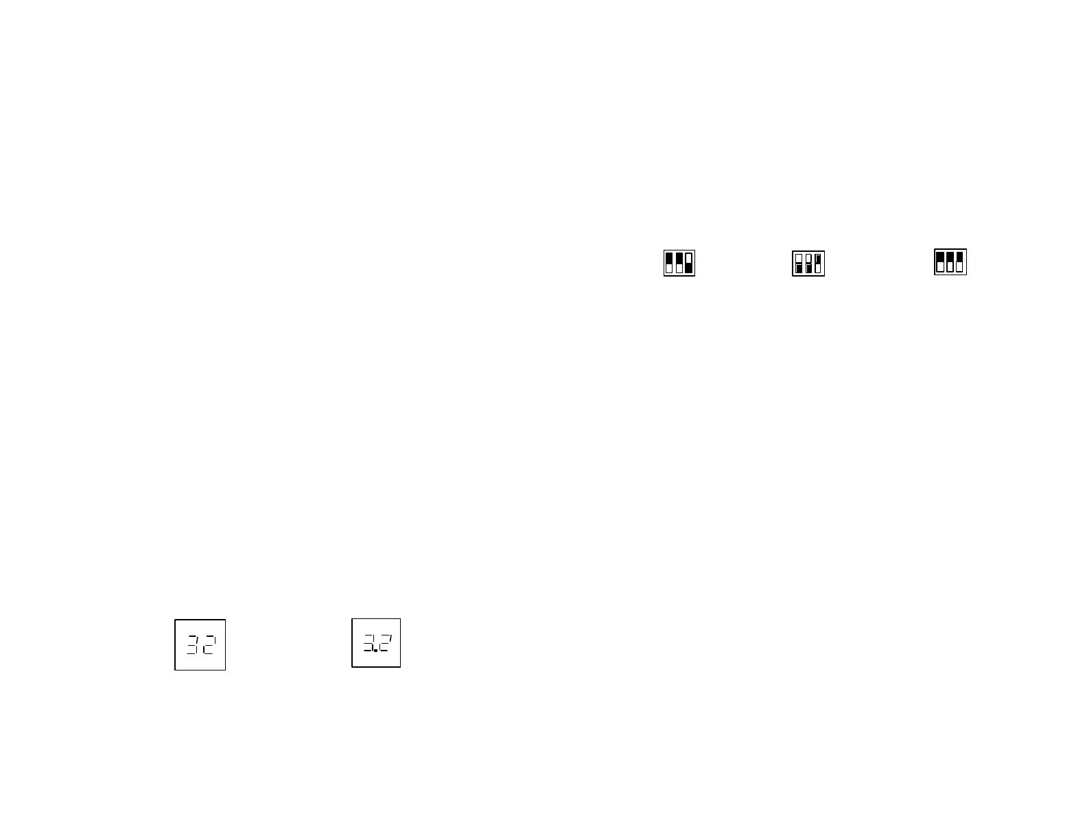
2. The channel display is a 2-digit display. When the selected channel is 2 digits, the display
will show the channel as selected. If the channel selected i s a 3 digit channel, the display will
show the last two digits of the selected channel with a dot between the two digits. The third
digit “1” will not be shown. See Figure C.
Channel 32 Channel 132
Figure C
Channel Range Settings
The dipsw itches on the front panel of the HS-V M1100 modulator are used to select the
range of channels available. See figure A.
There are three settings for the dipsw itches, UHF only, CA TV Ultra only and UHF/CA TV
Ultra. See Figure D. The modulator is preset to the CA TV Ultra, Channels 65 to 135.
UHF Band CATV Ultra Band UHF and CA TV Ultra
CH14-78 CH65-135 CH14-39, 91-135
Figure D
Warning:
Unplug the AC adapter from the HS-VM 1100 before changing the DIP switch settings.
Specifications for HS-VM 1100 Modulator
Output Frequency Range: 470MHz – 860MHz
Output Channels: UHF: CH14-78, CA TV : CH65-135
Video Frequency Response: +/- 1dB
Aural Intercarriers Stability: 4.5MHz w /n +/- 3KHz
Video Input Imp/RF Output Imp: 75 Ohm
Audio Input Impedance: >10K Ohm
Frequency Accuracy/Stability: PLL Crystal Stabilized +/- 5KHz
Video Input Level: 1Vp-p
Audio THD: 0.4%
Output Level: +10dBmV
Video Mod Index: 70% +/- 10%
Dual Sideband Aural/Visual Carrier Ratio: -15dB
Video S/N Ratio/A udio S/N Ratio: 52dB/50dB
Size: 95 x 75 x 26 mm (L x W x H)
3 ¾ x 3 x 1 in.
Weight (approx. w /o adapter): 115 grams (4 oz.)
Pow er A dapter (Input): 120VA C, 60Hz, 6W
(Output): 12V DC, 250mA
1
0
1 2 3
1
0
1 2 3
1
0
1 2 3
 Loading...