User Manual PS 278 / Issue 2 © 1996 ASL Intercom, Utrecht, Holland.
4
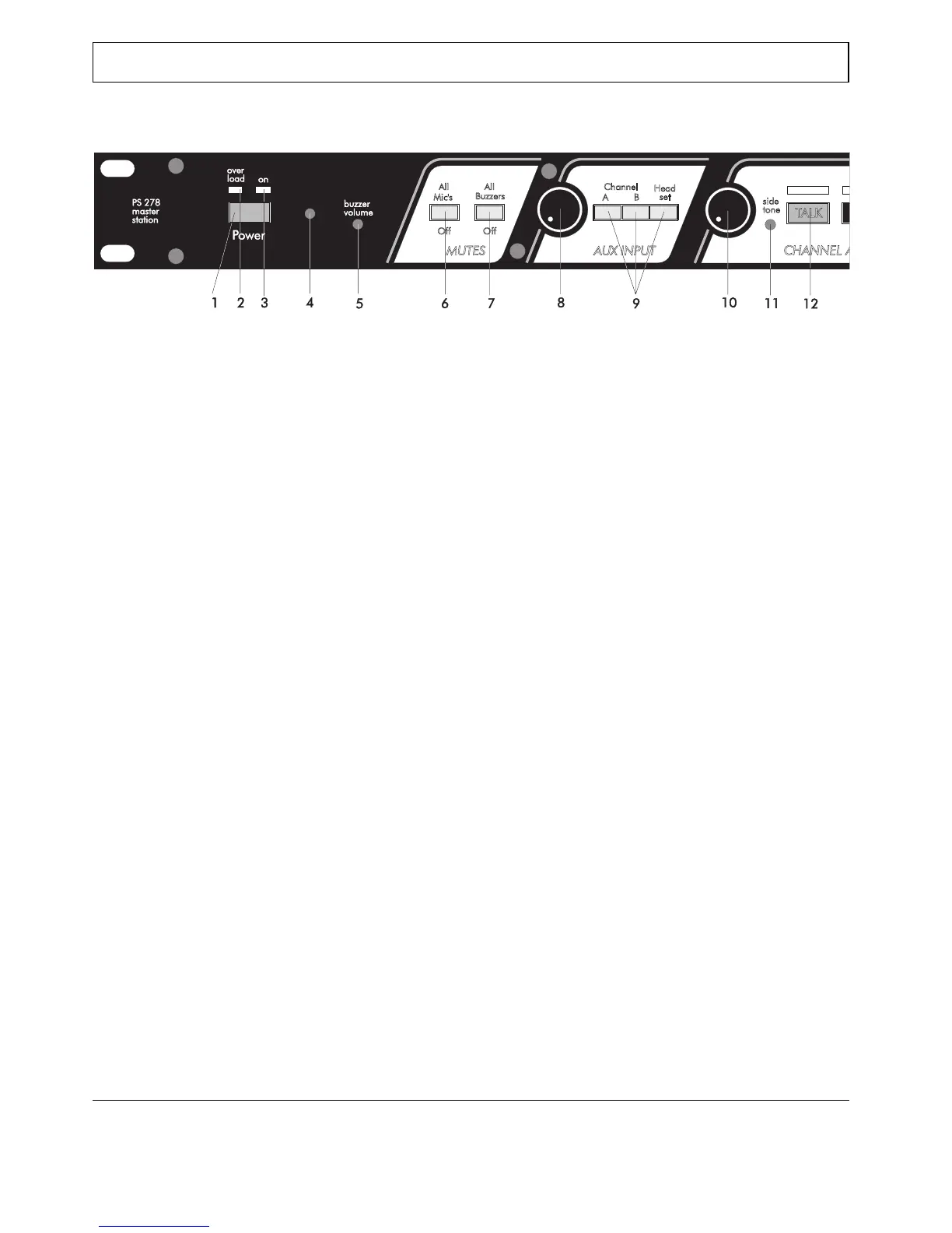
5.0 FRONT PANEL CONTROLS
1 POWER ON/OFF switch 7 ALL BUZZERS ON/OFF button
Mains power push button for switching ON and OFF With this button all buzzers of the connected stations
the internal power supply. can be muted.
2 OVERLOAD LED 8 AUX VOLUME control knob
This LED illuminates if the internal power supply has This knob adjusts the level of the aux input signal
shut off line power due to overload. before it is sent either to the intercom line(s) or to the
If the internal power supply is overloaded (too many headset (see also section 5.8).
user stations are connected, or short-circuit in the
interconnecting cables, or thermal overload), it
activates a circuit-breaker which immediately shuts off These three switches route the aux input signal to
line power. This circuit breaker resets automatically either:
3 seconds after the overload situation is terminated, 1) Intercom channel A and/or Intercom channel B
restoring line power automatically. 2) Directly to the headset
During short-circuit, the LED will flash every 3 If the aux is routed to the headset the aux is for local
seconds. During thermal overload it will remain on monitoring only, and can not be routed to the intercom
continuously. channels.
The LED will also come on for a few seconds every
time you switch on the mains power.
3 POWER LED
This LED illuminates if line power is supplied by the
internal power supply.
4 BUZZER
This buzzer indicates an incoming our outgoing call.
It is activated by pressing a CALL button of the PS 278
or a CALL button of any other station on channel A or
B for longer than two seconds and the buzzers are not
muted (see 5.7). You can adjust its volume with the
buzzer volume control.
5 BUZZER VOLUME trimmer
This trimmer adjusts the volume of the buzzer.
6 ALL MIC'S ON/OFF button
With this pushbutton all microphones of the connected
stations can be muted.
9 A/B/HEADSET routing switches