V400 – Installation Guide
U-0398-0607.doc – Issue: 03 complete, approved
Page 21 of 24
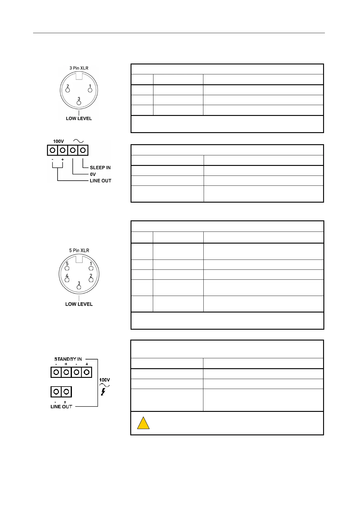
NSINT CONNECTIONS
AUDIO INPUT: 3-PIN XLR (FEMALE)
Pin No Signal Description
1 Signal common Cable screen (see Note below)
2 Audio I/P + Balanced audio input at 0 dBu
3 Audio I/P - Balanced audio input at 0 dBu
For best EMC performance, always connect cable screen to the back shell of
the connector.
100 V CONNECTIONS: 4-WAY PLUGGABLE WAGO CAGE CLAMP (FEMALE)
Signal Description
LINE OUT 100 V line audio output to loudspeaker circuit
0V Return path for SLEEP IN control input
SLEEP IN
Control input for activation of amplifier “Sleep”
function (requiring contact closure to 0 V)
LSIDC CONNECTIONS
AUDIO INPUT AND STANDBY CONNECTIONS: 5-PIN XLR (FEMALE)
Pin No Signal Description
1 STANDBY LOCKOUT
Bi-directional signal control line; prevents multiple
amplifiers accessing one standby amplifier
2 AUDIO IN + (HOT) Balanced audio input at 0 dBu
3 AUDIO IN - (COLD) Balanced audio input at 0 dBu
4
STANDBY OUT +
(HOT)
Balanced audio output to standby amplifier at 0 dBu
5
STANDBY OUT -
(COLD)
Balanced audio output to standby amplifier at 0 dBu
For best EMC performance, always connect cable screen to the back shell of
the connector.
100 V STANDBY CONNECTION: 4-WAY PLUGGABLE WAGO CAGE CLAMP (MALE)
100 V LOUDSPEAKER CONNECTION: 2-WAY PLUGGABLE WAGO CAGE CLAMP (MALE)
Signal Description
LINE OUT + 100 V line audio output to loudspeaker circuit
LINE OUT + 100 V line audio output to loudspeaker circuit
STANDBY IN
100 V line audio circuit from standby amplifier. Two
sets of connections are provided for 'daisy-chain'
wiring from mainframe to mainframe
!
!
Ensure +/- phase is preserved.
 Loading...