10
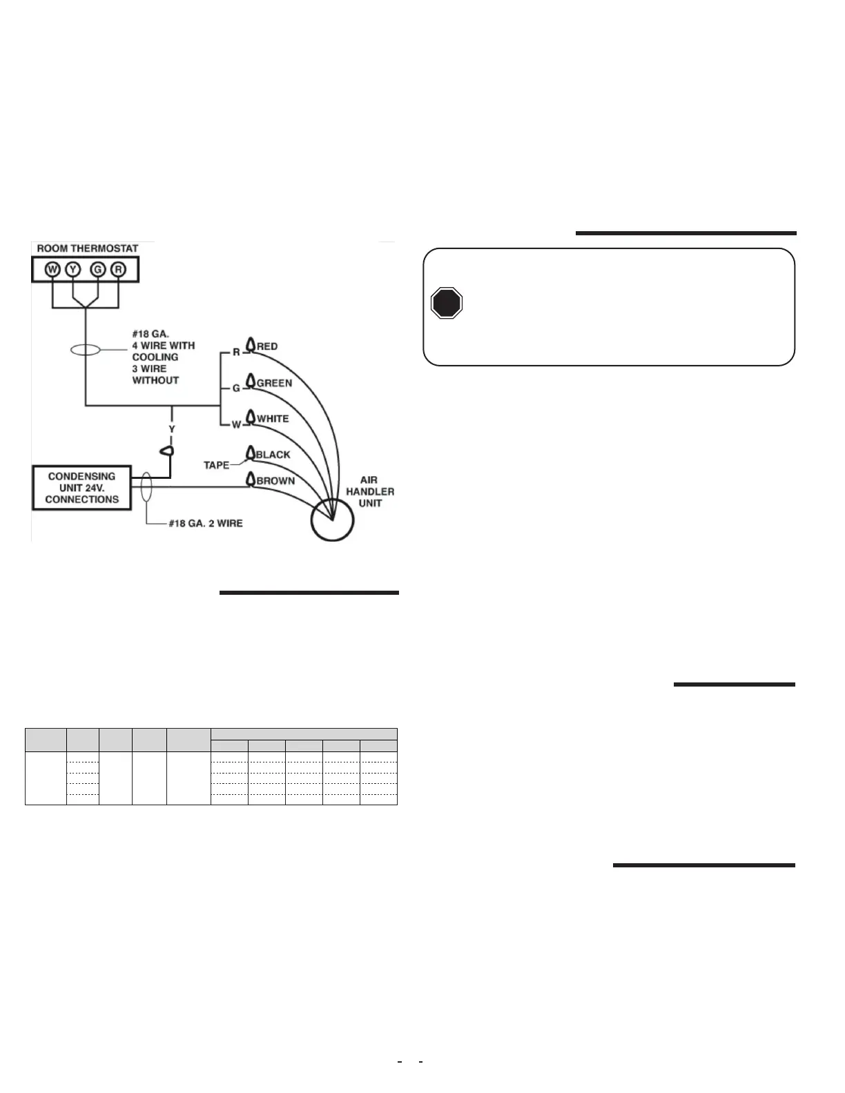
During cooling mode operation, the indoor blower G wire will ener-
gize a time delay relay inside the electric furnace. After a short time
delay period, the time delay relay contacts will close and apply power
to the blower motor. Fan delay periods are 7 seconds ON delay and
65 seconds OFF delay. (See Schematic)
The Y wire from the thermostat is not connected at the electric fur-
nace. This wire goes directly to the outdoor unit 24 volt wiring to turn
on the outdoor condensing unit when a call for cooling takes place.
The 24 volt common for the outdoor unit circuits is connected at the
electric furnace Brown wire.
The electric heater low voltage wiring W terminal is wired directly
from the thermostat to the electric furnace. The blower will delay a
heat call ON for a period of 5 seconds. The OFF delay period is 60
seconds.
Fig 5A-2.
Table 6-1.
Air volume needs to be set to the level recommended by the outdoor
unit equipment manufacturer. Most systems will require around 400
CFM of indoor air for every 1 ton of system cooling capacity. The air
volume must be set prior to attempting system charge.
This electric furnace uses a 240V PSC motor. The air volume level
produced by the electric furnaces at varying external static pressure
levels is shown in Table 6-1.
6. Air Volume Adjustment
Use a Magnehelic Gauge with a 1” scale and two static pressure
tips to measure the static pressure during the air volume adjustment
procedure. The high port static pressure tip should be placed in the
supply duct near the outlet of the electric furnace. The low port static
pressure tip should be placed in the return air duct near the entrance
to the electric furnace. The factory provided air lter should be in
place inside of the electric furnace.
1. Select a starting speed tap from the CFM table.
2. Call for fan only operation at the thermostat.
3. Read the external static pressure level on the Magnehelic gauge.
4. Make speed tap selection changes to get the air volume as close
as possible to the required level.
5. If the static pressure is above .5” wc , excessive turbulence or duct
friction needs to be reduced. (Obstructions in the duct system can
also cause excessive static pressure.)
6. When proper air volume is established, move on to the charging
procedure.
MODEL
SPEED
TAP
MOTOR
HP
MOTOR
AMPS
MOTOR
VOLTAGE
CFM V. EXTERNAL STATIC*
0.10 0.20 0.30 0.40 0.50
AE(U/D)
T1
3/4 5.4 240
940 850 795 740 640
T2 1155 1070 1015 950 885
T3 1375 1305 1255 1180 1127
T4 1500 1430 1375 1315 1260
T5 1850 1800 1760 1710 1650
1. Bring airow up to the maximum CFM possible according to Table
6-1.
2. Evacuate refrigeration system to micron level required by outdoor
unit manufacturer.
3. Release system charge from outdoor unit and call for cooling.
4. Use outdoor unit equipment manufacturer specic charging charts
if available and make proper charge adjustment based upon outdoor
unit instructions.
5. If outdoor unit instructions and charts are not available, use Aspen
provided charts. Make certain indoor air temperature is near comfort
level setpoint 75F, prior to establishing superheat and subcooling
levels.
7. System Charging
An improperly charged system may cause degradation in sys-
tem performance and damage the compressor. After installation
of the coil, refer to the outdoor unit manufac-
turer for charging techniques and amount of
charge. If outdoor unit manufacturers charg-
ing instructions are unavailable; then refer to instructions below
to charge the system.
CAUTION
!
After all connections are made, start-up and checkout must be per-
formed before proper evaluation of the entire system can be made.
Make sure that heat anticipator is properly set as noted on thermo-
stat instructions. Load requirements can vary in each residence and
it may be necessary for the installer or homeowner to make slight ad-
justments to the heat anticipator setting for longer or shorter cycles.
It is recommended to change the setting no more than plus or minus
0.05 amps at a time. Greater changes can cause the unit to rapid
cycle or remain on excessively. Measure anticipator circuit current
with electric heaters energized and set anticipator to proper level.
8. Adjustment Of Heat Anticipator
9. Final System Checkout
1. Make certain all cabinet openings are properly sealed and any
grommets moved during installation are moved into proper place.
2. With cooling system operating, check for condensate leakage.
3. Perform leak detection inspection of refrigerant circuit and con-
necting piping.
4. Secure all cabinet doors
 Loading...