9
Line voltage wiring should be
routed through the access holes
at the top of the electric fur-
nace. Proper electrical conduit
connection ttings should be
used. Connect the power wiring
to the line side connections on
the electric furnace. The electri-
cal ground wire should be con-
nected to the grounding lug.
Ensure both the eld supplied
ground wire and electric furnace
GREEN ground wire are both
secured to the grounding lug of
the electric furnace.
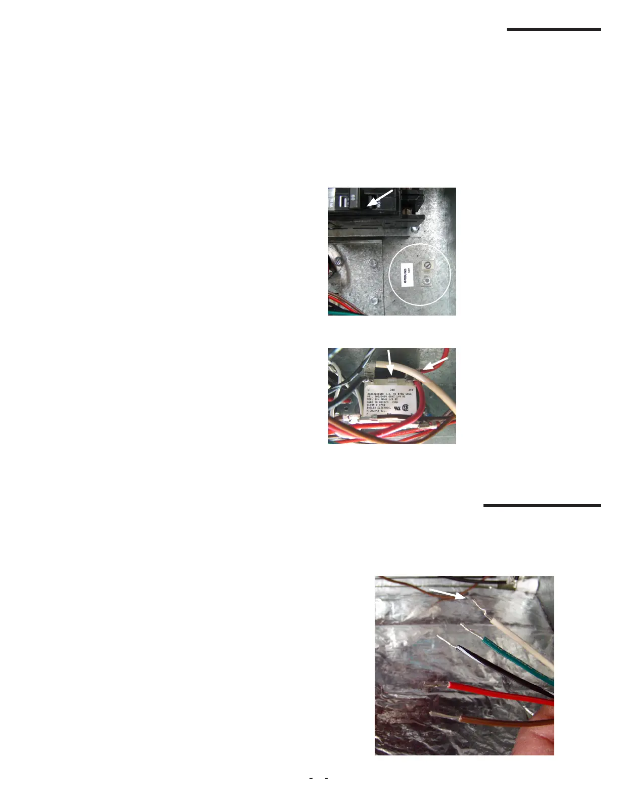
If the line voltage being sup-
plied to the electric furnace is
208 volt single phase, the line
voltage tap on the low voltage
transformer needs to be moved
from the 240 volt tap to the 208
volt tap. If this is not done, the
secondary output voltage of the
transformer will be too low.
208VAC
Tap
240VAC
Tap
5A. Single Stage Cooling with Electric Heat
5. Low Voltage Connections
The electric furnace comes factory setup for a single stage cool-
ing system. If factory installed accessory electric heaters are prein-
stalled, the unit will also have a low voltage wire for the electric heat
(Fig 5A-1).
Fig 5A-1.
4. Electrical Line Voltage Wiring
These units are designed for single or three phase 208/240 volts, 60
HZ power supply. Wire selection and wiring must be in accordance
with the National Electric Code and/or local codes. Unit terminals are
designed to accommodate copper and aluminum wiring. If aluminum
wiring is used: please observe special precautions relative to sizing,
wire connections and corrosion protection.
All models with 5,8 or 10 kW electric heat are arranged for single
circuit connections. Models larger than 10 kW are arranged for multi-
circuit protection. Refer to top part of wiring diagram at the end of this
guide for detailed information.
- Insulate between the oor base and the oor when used on a com-
bustible oor. Be sure to cut the insulation around the perimeter of
the duct connector opening.
- Install the oor base over the oor opening with the anges on the
11 x 13 inch opening facing down.
- Use four screws to secure the oor base to the oor.
It is recommended that wherever supply and return air sheet metal
ducts pass through unconditioned areas, they be insulated to pre-
vent excessive heat loss during heating operation. When applied in
conjunction with summer air conditioning, sheet metal duct routed
through unconditioned areas should be insulated and have an out-
side vapor barrier to prevent formation of condensation.
3C. Ductwork and Duct Connector
Duct systems should be installed in accordance with standards for
air-conditioning systems, National Fire Protection Association Pam-
phlet No. 90A or 90B. They should be sized in accordance with Na-
tional Environmental System Contractors Association Manual K, or
whichever is applicable. It is recommended that installers refer to
the “Manufactured Housing Duct System Guide to Best Practices”
by MHI-MHRA.
On any job, non-ammable exible collars should be used for the
return air and discharge connections to prevent transmission of vi-
bration. Although these units have been specially designed for quiet,
vibration-free operation, air ducts can act as soundboards if poorly
installed.
All main supply and return air drops should be properly sized as
determined by the designer of the duct system and should not nec-
essarily be the size of the duct ange openings of the unit. (The duct
size should never be smaller than the ange openings of the electric
furnace supply and return air openings.)
To install the duct connector:
- Attach duct connector foam gasket along the perimeter of the duct
opening to seal the duct connector to the top of the duct.
- To connect the duct connector, insert it into the oor opening and
bend back the tabs inside the duct. Fold the tabs over 90 degrees to
ensure a secure connection. Seal around the duct connector.
- Slit the corners of the duct connector that stick up above the oor,
and then bend the sides over onto the oor surface.
 Loading...