OM00017 Rev B, FP00066, FP00102 Operation Manual – March 24, 2023 Page 7 of 10
Note: In some conditions, the compressor will reach its nominal current limit. This condition is most
likely in warmer ambient conditions. A 24V compressor will limit at (15 A), which will cause the
compressor to reduce speed until the current drops to 15 A. The 48V compressor will limit at 10A and
will lower compressor speed until the current reaches 10A.
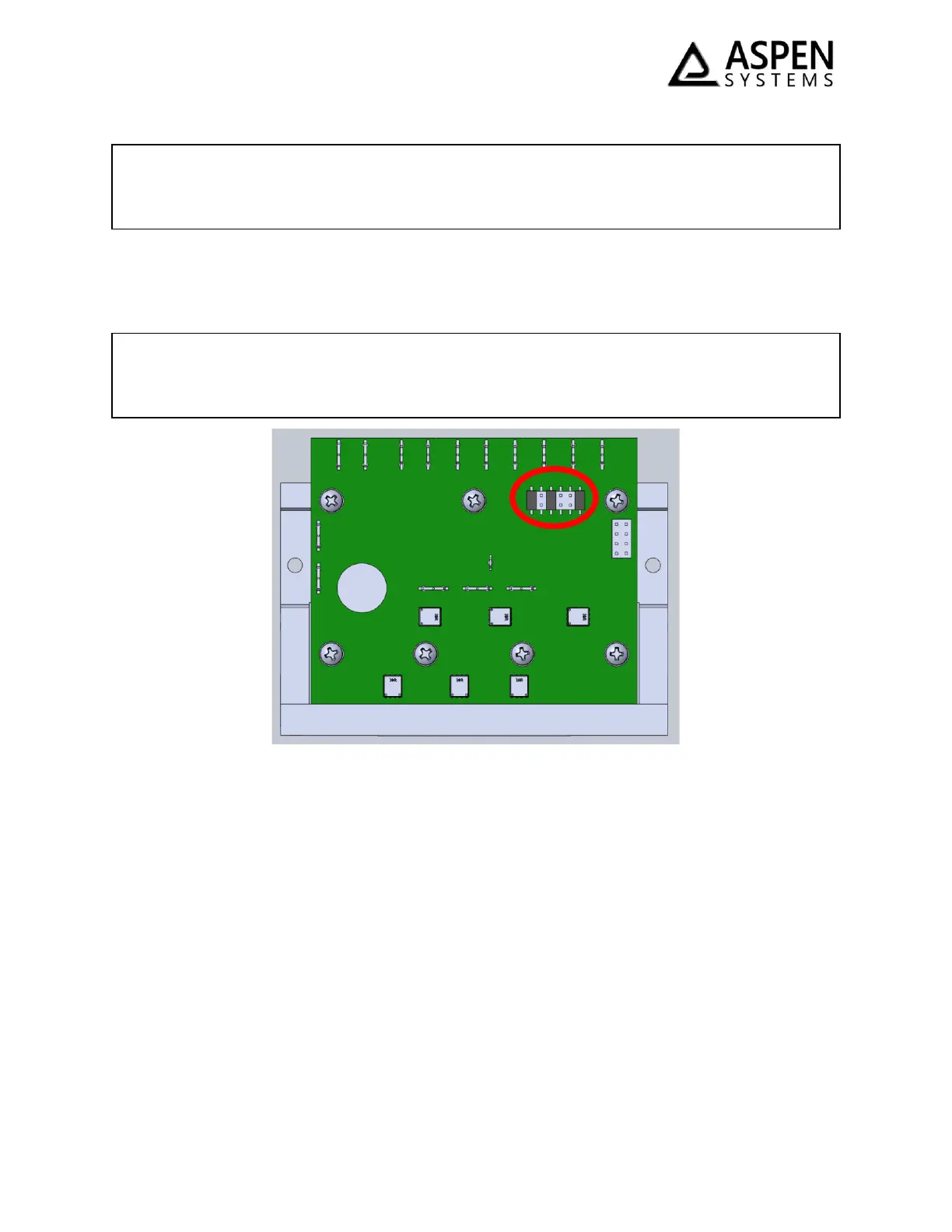
Figure 3 – FP00102 & FP00066 Drive-Board Jumper Configuration
The FP00102/ FP00066 drive-board default jumper configuration is shown in the image above. More
information about jumper settings and the driveboard functionality is located in the appendix.
Performance
The performance curve below (Figure 4) defines the performance of the LCM. The data shown below is
derived using 2 L/min water flow and a 30% glycol solution for subzero operation.
CAUTION! Aspen recommends the following operating sequence: (1) power on the drive board, (2)
ground the enable line (3) apply a speed signal to run the compressor. Applying power to the drive
board while the enable line is grounded may result in high in-rush currents
CAUTION! Power and phase wires are not intended for repeated connection and disconnection.
Multiple connections and disconnections of these wires to the board can result in poor electrical
contact, leading to cable overheating and system damage.
 Loading...