X570D4U-2L2T / X570D4U
30 31
English
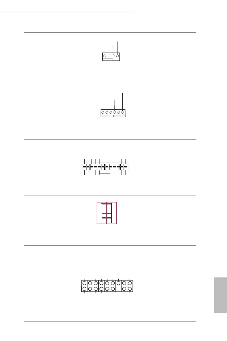
System Fan Connectors
(4-pin FAN1)
(see p.7, No. 26)
(4-pin FAN2)
(see p.7, No. 27)
(4-pin FAN3)
(see p.7, No. 5)
(6-pin FAN4)
(see p.7, No. 6)
(6-pin FAN5)
(see p.7, No. 7)
(6-pin FAN6)
(see p.7, No. 9)
FAN_SPEED
GND
FAN_VOLTAGE
1234
FAN_SPEED
FAN_SPEED_CONTROL
FAN_VOLTAGE
GND
12 3456
SENSOR
NC
Please connect fan cables to the
fan connectors and match the
black wire to the ground pin.
All fans support Fan Control.
ATX Power Connector
(24-pin ATXPWR1)
(see p.7, No. 4)
3V
3V
GND
GND
5V
5V
GND
PWROK_PS
5VSB
12V
12V
3V
121
13
24
3V
-12V
GND
PSON#
GND
GND
GND
5V
5V
5V
GND
N/A
is motherboard provides a
24-pin ATX power connector.
To use a 20-pin ATX power
supply, please plug it along Pin
1 and Pin 13.
ATX 12V Power
Connectors
(8-pin ATX12V3)
(see p.7, No. 1)
48
15
12V
GND
is motherboard provides
one 8-pin ATX 12V power
connector.
TPM Header
(17-pin TPM1)
(see p.7, No. 28)
is connector supports
Trusted Platform Module
(TPM) system, which can
securely store keys, digital
certicates, passwords, and
data. A TPM system also helps
enhance network security,
protects digital identities, and
ensures platform integrity.
1
LFRAME#_L
CK_33M_TPM
TPM_RST#
LAD3_L
+3V
LAD0_L
+3VSB
GNDF_CLKRUN#
SERIRQ#
S_PWRDWN#
GND
LAD1_L
LAD2_L
SMB_DATA_MAIN
SMB_CLK_MAIN
GND
 Loading...