2
ASRock A55 Pro3 Motherboard
English
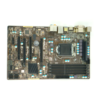
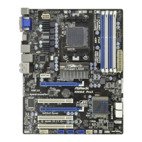
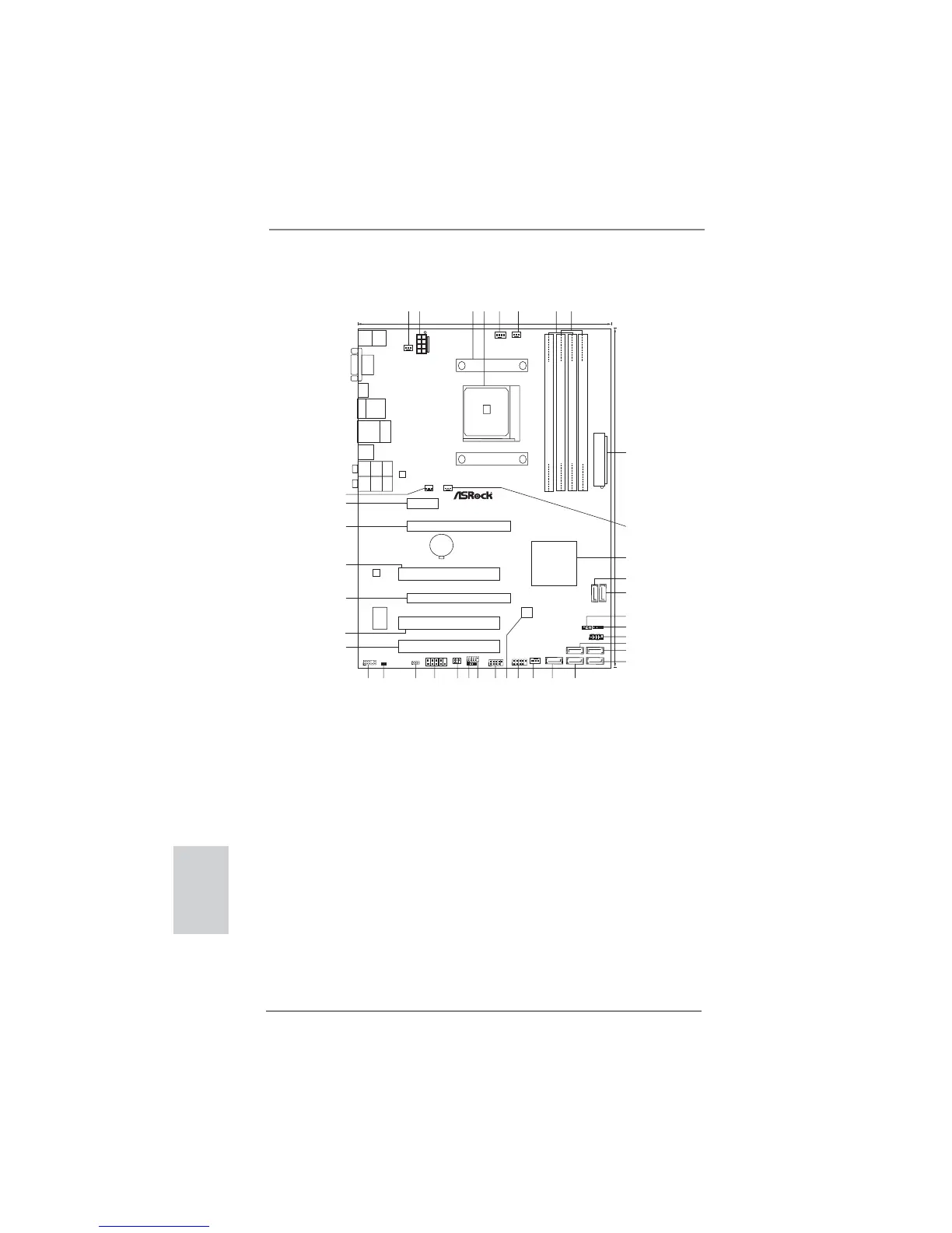
Motherboard Layout
1 Power Fan Connector (PWR_FAN1) 20 SATA2 Connector (SATA2_2, Blue)
2 ATX 12V Power Connector (ATX12V1) 21 SATA2 Connector (SATA2_1, Blue)
3 CPU Heatsink Retention Module 22 Chassis Fan Connector (CHA_FAN1)
4 CPU Socket 23 USB 2.0 Header (USB10_11, Blue)
5 CPU Fan Connector (CPU_FAN1) 24 SPI Flash Memory (32Mb)
6 CPU Fan Connector (CPU_FAN2) 25 USB 2.0 Header (USB8_9, Blue)
7 2 x 240-pin DDR3 DIMM Slots 26 USB 2.0 Header (USB6_7, Blue)
(Dual Channel A: DDR3_A1, DDR3_B1; Blue) 27 Consumer Infrared Module Header (CIR1)
8 2 x 240-pin DDR3 DIMM Slots 28 Infrared Module Header (IR1)
(Dual Channel B: DDR3_A2, DDR3_B2; White) 29 COM Port Header (COM1)
9 ATX Power Connector (ATXPWR1) 30 Clear CMOS Jumper (CLRCMOS1)
10 Chassis Fan Connector (CHA_FAN3) 31 HDMI_SPDIF Header (HDMI_SPDIF1, White)
11 Southbridge Controller 32 Front Panel Audio Header (HD_AUDIO1, White)
12 SATA3 Connector (SATA3_1, White) 33 PCI Slot (PCI3)
13 SATA3 Connector (SATA3_2, White) 34 PCI Slot (PCI2)
14 Power LED Header (PLED1) 35 PCI Express 2.0 x16 Slot (PCIE3; Blue)
15 Chassis Speaker Header (SPEAKER 1, White) 36 PCI Slot (PCI1)
16 System Panel Header (PANEL1, White) 37 PCI Express 2.0 x16 Slot (PCIE2; Blue)
17 SATA2 Connector (SATA2_3, Blue) 38 PCI Express 2.0 x1 Slot (PCIE1; White)
18 SATA2 Connector (SATA2_5, Blue) 39 Chassis Fan Connector (CHA_FAN2)
19 SATA2 Connector (SATA2_4, Blue)
Super
I/O
CMOS
BATTERY
ATXPWR1
AMD
A55 FCH
(Hudson-D2)
Chipset
COM1
PCIE1
PCI1
LAN
AUDIO
CODEC
1
CLRCMOS1
1
CPU_FAN1
HDLED RESET
PLED PWRBTN
1
PANEL1
CHA_FAN1
SPEAKER1
1
HD_AUDIO1
1
30.5cm (12.0-in)
21.8cm (8.6-in)
6
7
1
2
4
3
5
8
9
10
11
12
13
14
15
16
17
18
19
20
2122
23
24
2526
272829
32Mb
BIOS
IR1
1
HDMI1
Top :
CTR BASS
Center:
REAR SPK
Bottom:
Optical
SPDIF
Top:
LINE IN
Center:
FRONT
Bottom:
MIC IN
1
USB6_7
CPU_FAN2
A55 Pro3
ErP/EuP Ready
RoHS
DDR3 2400+
CIR1
1
ATX12V1
DX11
SOCKET FM1
PLED1
1
DDR3_A1 (64 bit, 240-pin module)
DDR3_A2 (64 bit, 240-pin module)
DDR3_B1 (64 bit, 240-pin module)
DDR3_B2 (64 bit, 240-pin module)
PWR_FAN1
1
HDMI_SPDIF1
1
USB8_9
1
USB10_11
VGA1
USB 2.0
T: U SB 4
B: USB5
eSATA1
Top:
RJ-45
USB 2.0
T:USB0
B: USB1
CHA_FAN3
CHA_FAN2
303132
33
34
35
36
37
39
SATA2_1
X
Fast USB
Designed in Taipei
Dual Graphics
PCIE2
PCIE3
PCI2
PCI3
SATA2_2
SATA2_4
SATA2_3
SATA2_5
SATA3_2SATA3_1
PS2
Mouse
PS2
Keyboard
USB 3.0
T:USB2
B: USB3
USB 3.0
SATA3 6Gb/s
HDMI 1.4a
38
 Loading...