1313
1313
13
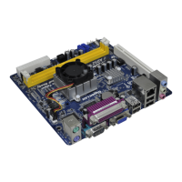
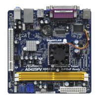
ASRock AD525PV3 / AD425PV3 Motherboard
1. High Definition Audio supports Jack Sensing, but the panel wire on
the chassis must support HDA to function correctly. Please follow the
instruction in our manual and chassis manual to install your system.
2. If you use AC’97 audio panel, please install it to the front panel audio
header as below:
A. Connect Mic_IN (MIC) to MIC2_L.
B. Connect Audio_R (RIN) to OUT2_R and Audio_L (LIN) to OUT2_L.
C. Connect Ground (GND) to Ground (GND).
D. MIC_RET and OUT_RET are for HD audio panel only. You don’t
need to connect them for AC’97 audio panel.
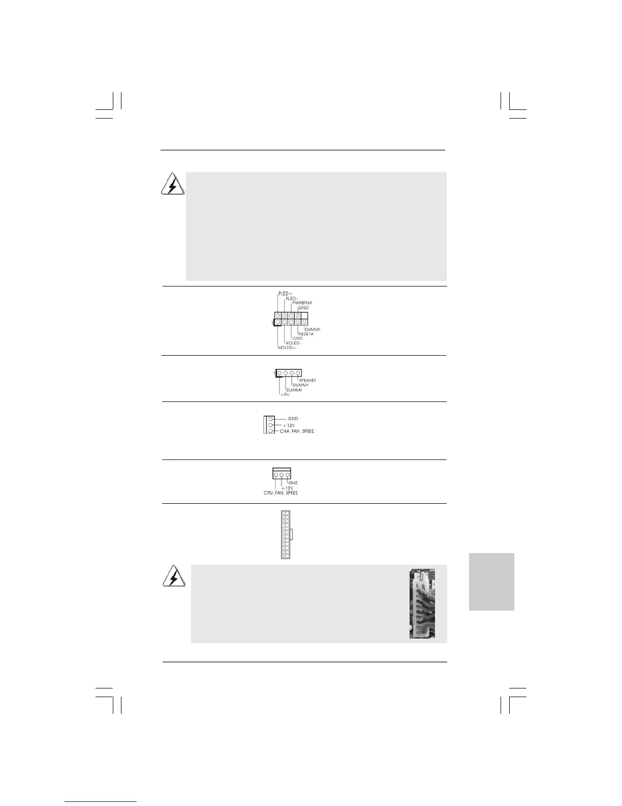
System Panel Header This header accommodates
(9-pin PANEL1) several system front panel
(see p.2 No. 11) functions.
Chassis Speaker Header Please connect the chassis
(4-pin SPEAKER 1) speaker to this header.
(see p.2 No. 12)
Chassis Fan Connector Please connect a chassis fan
(3-pin CHA_FAN1) cable to this connector and
(see p.2 No. 6) match the black wire to the
ground pin.
CPU Fan Connector Please connect a CPU fan cable
(3-pin CPU_FAN1) to this connector and match
(see p.2 No. 1) the black wire to the ground pin.
EnglishEnglish
EnglishEnglish
English
20-Pin ATX Power Supply Installation
ATX Power Connector Please connect an ATX power
(24-pin ATXPWR1) supply to this connector.
(see p.2, No. 5)
Though this motherboard provides 24-pin ATX power connector,
it can still work if you adopt a traditional 20-pin ATX power supply.
To use the 20-pin ATX power supply, please plug your power
supply along with Pin 1 and Pin 13.
12
1
24
13
12
1
24
13
 Loading...