1212
1212
12
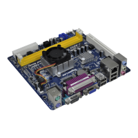
ASRock AM2NF6G-VSTA Motherboard
EnglishEnglish
EnglishEnglish
English
2.32.3
2.32.3
2.3
Expansion SlotsExpansion Slots
Expansion SlotsExpansion Slots
Expansion Slots
(PCI Express Slots, PCI Slots and HDMR Slot)(PCI Express Slots, PCI Slots and HDMR Slot)
(PCI Express Slots, PCI Slots and HDMR Slot)(PCI Express Slots, PCI Slots and HDMR Slot)
(PCI Express Slots, PCI Slots and HDMR Slot)
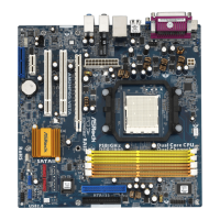
There are 2 PCI Express slots, 2 PCI slots and 1 HDMR slot on AM2NF6G-VSTA
motherboard.
PCIE Slots: PCIE1 (PCI Express Graphics slot) is used for PCI Express cards with
x16 lane width graphics cards.
PCIE2 (PCIE x1 slot) is used for PCI Express cards with x1 lane
width cards, such as Gigabit LAN card, SATA2 card, etc.
PCIE1 (PCI Express Graphics slot) supports most of the ATi
TM
and NVIDIA
®
graphics cards except some old version ATi
TM
graphics cards, such as ATi
TM
X300,
X550, X700, and X800 series graphics cards.
PCI Slots: PCI slots are used to install expansion cards that have the 32-bit PCI
interface.
HDMR slot: The HDMR slot is used to insert an ASRock HDMR card with v.92
Modem functionality. The HDMR slot is shared with PCIE2 slot; you
can only choose either PCIE2 slot or HDMR slot to use.
Installing an expansion cardInstalling an expansion card
Installing an expansion cardInstalling an expansion card
Installing an expansion card
Step 1. Before installing the expansion card, please make sure that the power
supply is switched off or the power cord is unplugged. Please read the
documentation of the expansion card and make necessary hardware
settings for the card before you start the installation.
Step 2. Remove the system unit cover (if your motherboard is already installed in
a chassis).
Step 3. Remove the bracket facing the slot that you intend to use. Keep the
screws for later use.
Step 4. Align the card connector with the slot and press firmly until the card is
completely seated on the slot.
Step 5. Fasten the card to the chassis with screws.
Step 6. Replace the system cover.
 Loading...