22
English
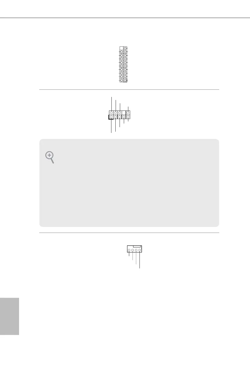
USB 3.1 Gen1 Header
(19-pin USB3_3_4)
(see p.1, No. 7)
ere is one header on
this motherboard. is
USB 3.1 Gen1 header can
support two ports.
Front Panel Audio Header
(9-pin HD_AUDIO1)
(see p.1, No. 22)
is header is for
connecting audio devices
to the front audio panel.
Chassis Fan / Waterpump
Fan Connectors
(4-pin CHA_FAN1/WP)
(see p.1, No. 17)
(4-pin CHA_FAN2/WP)
(see p.1, No. 2)
(4-pin CHA_FAN3/WP)
(see p.1, No. 16)
Please connect fan cables
to the fan connectors and
match the black wire to
the ground pin.
J_SENSE
OUT2_L
1
MIC_RET
PRESENCE#
GND
OUT2_R
MIC2_R
MIC2_L
OUT_RET
1. High Denition Audio supports Jack Sensing, but the panel wire on the chassis
must support HDA to function correctly. Please follow the instructions in our
manual and chassis manual to install your system.
2. If you use an AC’97 audio panel, please install it to the front panel audio header by
the steps below:
A. Connect Mic_IN (MIC) to MIC2_L.
B. Connect Audio_R (RIN) to OUT2_R and Audio_L (LIN) to OUT2_L.
C. Connect Ground (GND) to Ground (GND).
D. MIC_RET and OUT_RET are for the HD audio panel only. You don’t need to
connect them for the AC’97 audio panel.
E. To activate the front mic, go to the “FrontMic” Tab in the Realtek Control panel
and adjust “Recording Volume”.
1
IntA_PB_D+
Dummy
IntA_PB_D-
GND
IntA_PB_SSTX+
GND
IntA_PB_SSTX-
IntA_PB_SSRX+
IntA_PB_SSRX-
VbusVbus
Vbus
IntA_PA_SSRX-
IntA_PA_SSRX+
GND
IntA_PA_SSTX-
IntA_PA_SSTX+
GND
IntA_PA_D-
IntA_PA_D+
GND
FAN_VOLTAGE
CHA_FAN_SPEED
FAN_SPEED_CONTROL