B450M Pro4 R2.0
29
English
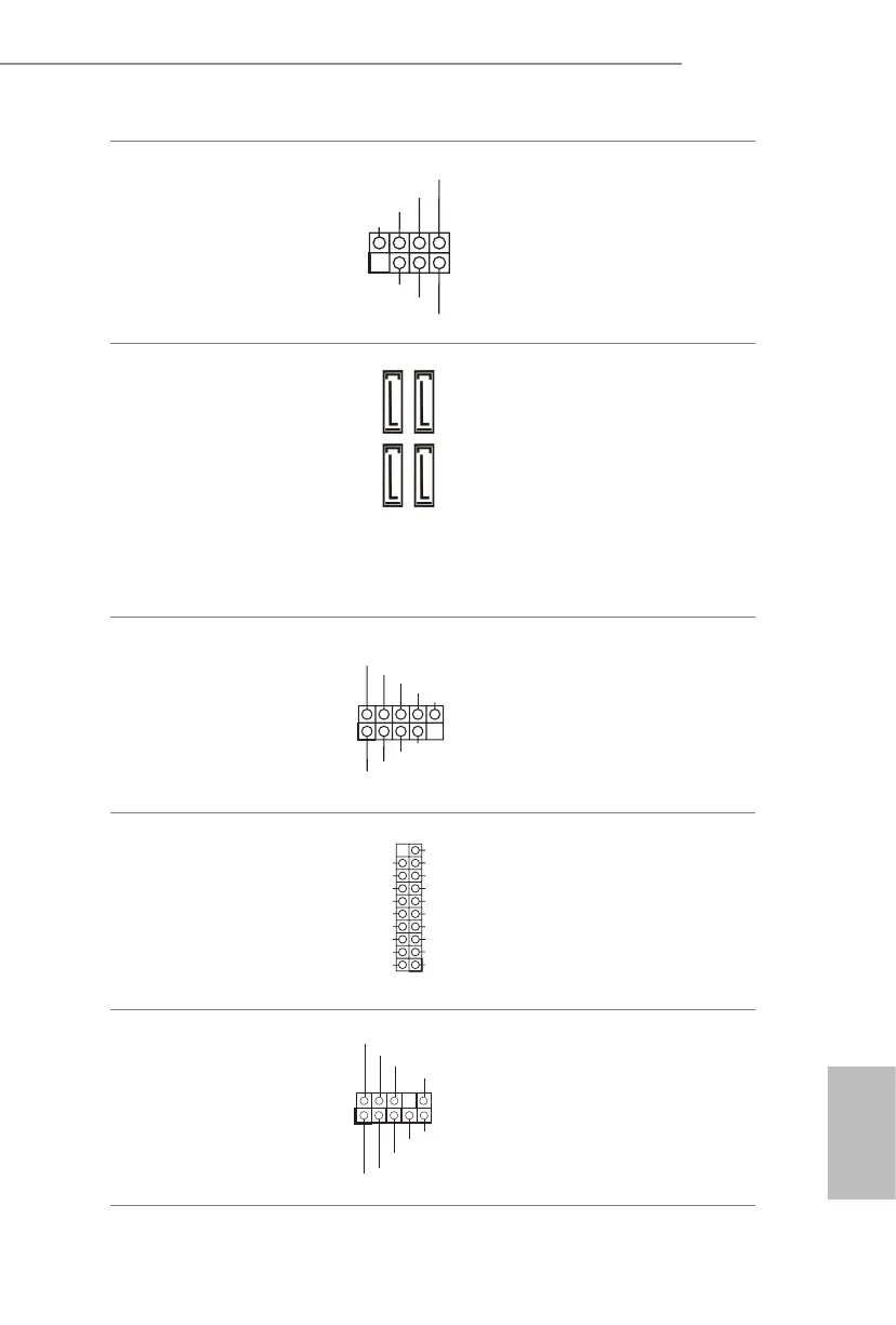
Power LED and Speaker
Header
(7-pin SPK_PLED1)
(see p.7, No. 14)
Please connect the
chassis power LED and
the chassis speaker to this
header.
Serial ATA3 Connectors
(SATA3_1:
see p.7, No. 12) (Upper)
(SATA3_2:
see p.7, No. 11) (Lower)
(SATA3_3:
see p.7, No. 9) (Upper)
(SATA3_4:
see p.7, No. 10) (Lower)
ese four SATA3
connectors support SATA
data cables for internal
storage devices with up to
6.0 Gb/s data transfer rate.
* M2_2 and SATA3_3
share lanes. If either one
of them is in use, the other
one will be disabled.
USB 2.0 Headers
(9-pin USB_3_4)
(see p.7, No. 20)
(9-pin USB_5_6)
(see p.7, No. 19)
ere are two headers
on this motherboard.
Each USB 2.0 header can
support two ports.
USB 3.2 Gen1 Header
(19-pin USB3_56)
(see p.7 or 8, No. 8)
ere is one header on
this motherboard. Each
USB 3.2 Gen1 header can
support two ports.
Front Panel Audio Header
(9-pin HD_AUDIO1)
(see p.7, No. 25)
is header is for
connecting audio devices
to the front audio panel.
1
+5V
DUMMY
PLED+
PLED+
DUMMY
SPEAKER
DUMMY
GND
GND
P+
P-
USB_PWR
P+
P-
USB_PWR
1
SATA3_3
SATA3_4
SATA3_1
SATA3_2
J _SENSE
O UT2_L
1
M IC_RET
P RESENCE#
GN D
O UT2_R
M IC2_R
M IC2_L
OUT_RET
1
IntA_ PB_D +
Dummy
IntA_ PB_D -
GND
IntA_ PB_S ST X +
GND
IntA_ PB_S ST X -
IntA_ PB_S SR X +
IntA_ PB_S SR X -
VbusVbus
Vbus
IntA_ PA_S SR X -
IntA_ PA_S SR X +
GND
IntA_ PA_S ST X -
IntA_ PA_S ST X +
GND
IntA_ PA_D -
IntA_ PA_D +
 Loading...