24
English
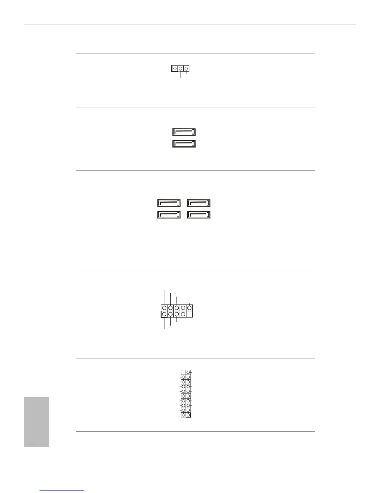
Power LED Header
(3-pin PLED1)
(see p.10, No. 15)
Please connect the chassis
power LED to this header
to
indicate the system’s
power status.
Serial ATA2 Connectors
(SATA2_0:
see p.10, No. 7)
(SATA2_1:
see p.10, No. 8)
ese two SATA2
connectors support SATA
data cables for internal
storage devices with up to
3.0 Gb/s data transfer rate.
Serial ATA3 Connectors
(SATA3_0:
see p.10, No. 9)
(SATA3_1:
see p.10, No. 14)
(SATA3_2:
see p.10, No. 11)
(SATA3_3:
see p.10, No. 10)
ese
four
SATA3
connectors support SATA
data cables for internal
storage devices with up to
6.0 Gb/s data transfer rate.
USB 2.0 Headers
(9-pin USB4_5)
(see p.10, No. 18)
(9-pin USB6_7)
(see p.10, No. 17)
Besides two USB 2.0 ports
on the I/O panel, there
are two headers on this
motherboard. Each USB
2.0 header can support
two ports.
USB 3.0 Headers
(19-pin USB3_2_3)
(see p.10, No. 6)
Besides four USB 3.0 ports
on the I/O panel, there
are one header on this
motherboard. Each USB
3.0 header can support
two ports.