C621A WS
32 33
English
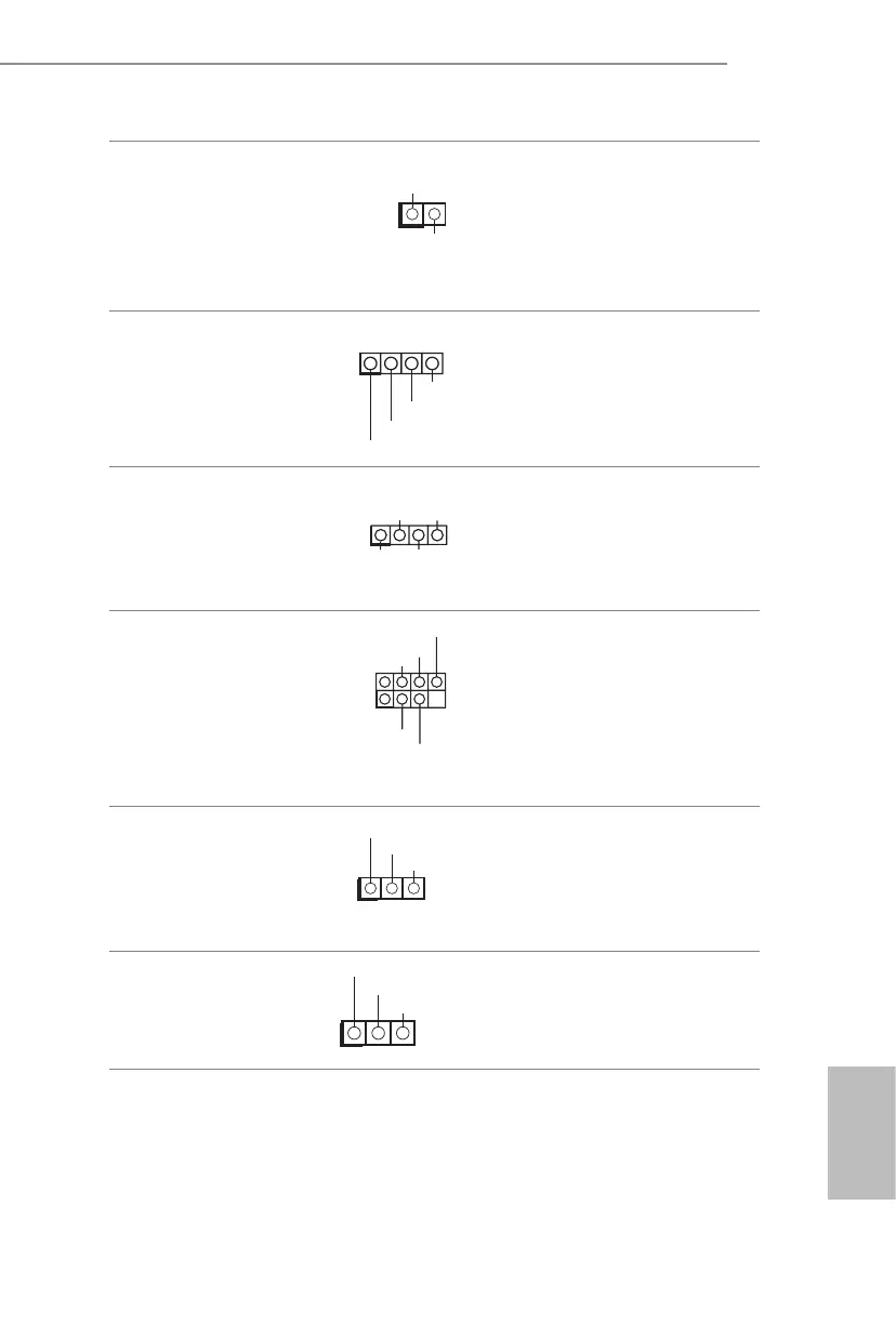
ermal Sensor Header
(2-pin TR1)
(see p.6, No. 39)
1
Please connect the thermal
sensor cable to either pin 1-2
or pin 2-3 and the other end to
the device which you wish to
monitor its temperature.
Front LAN LED Header
(4-pin FRONT_LED_
LAN34)
(see p.6, No. 35)
1
LAN4_LINK
LED_PWR
LED_PWR
is 4-pin connector is used
for the front LAN status
indicator.
Chassis Speaker Header
(4-pin SPEAK ER1)
(see p.6, No. 26)
1
+5V
DUMMY
DUMMY
SPEAKER
Please connect the chassis
speaker to this header.
Serial General Purpose
Input/Output Headers
(7-pin SATA_SGPIO1)
(see p.6, No. 37)
(7-pin SSATA_SGPIO1)
(see p.6, No. 38)
1
SLOAD
GND
SDATA OUT
e headers support Serial
Link interface for onboard
SATA connections.
PWM Conguration
Header
(3-pin PWM_CFG1)
(see p.6, No. 11)
SMB_DATA_VSB
SMB_CLK_VSB
1
is header is used for PWM
congurations.
CPU VSENSE Header
(3-pin CPU_VSENSE)
(see p.6, No. 10)
GND
GND
1
is header is used to detect
CPU1 VSENSE.
 Loading...