22
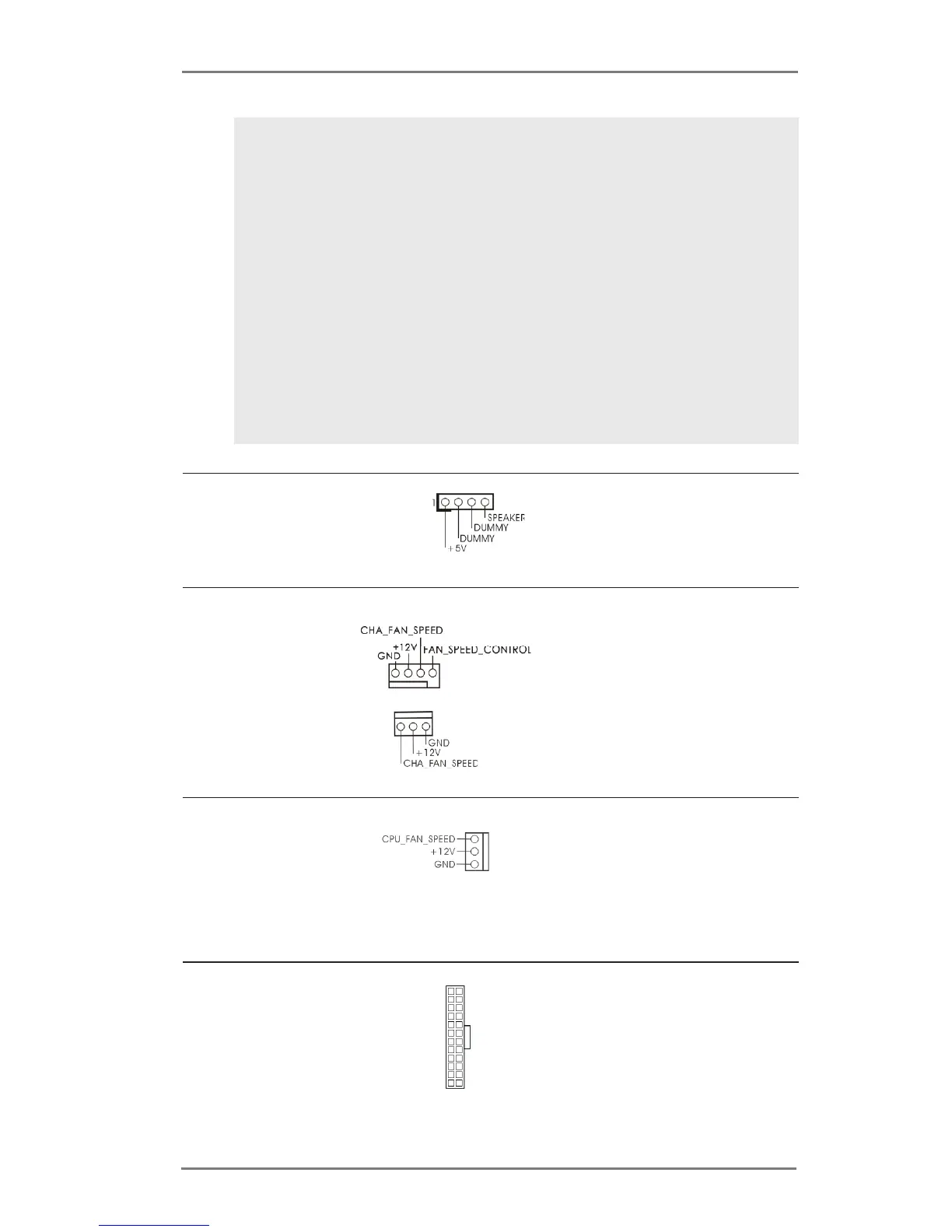
Chassis Speaker Header Please connect the chassis
(4-pin SPEAKER 1)
speaker to this header.
(see p.12 No. 15)
Chassis Fan Connectors Please connect the fan cables
(4-pin CHA_FAN1)
to the fan connectors and
(see p.12 No. 2)
match the black wire to the
ground pin. CHA_FAN2
supports fan speed control by
(3-pin CHA_FAN2)
fan power voltage.
(see p.12 No. 16)
CPU Fan Connectors Please connect the CPU fan
(3-pin CPU_FAN1)
cable to the connector and
(see p.12 No. 1)
match the black wire to the
ground pin. CPU_FAN1
supports fan speed control.
ATX Power Connector Please connect an ATX power
(24-pin ATXPWR1)
supply to this connector.
(see p.12 No. 7)
12
1
24
13
PLED (System Power LED):
Connect to the power status indicator on the chassis front panel. The LED
is on when the system is operating. The LED keeps blinking when the sys-
tem is in S1 sleep state. The LED is off when the system is in S3/S4 sleep
state or powered off (S5).
HDLED (Hard Drive Activity LED):
Connect to the hard drive activity LED on the chassis front panel. The LED
is on when the hard drive is reading or writing data.
The front panel design may differ by chassis. A front panel module mainly
consists of power switch, reset switch, power LED, hard drive activity LED,
speaker and etc. When connecting your chassis front panel module to this
header, make sure the wire assignments and the pin assign-ments are
matched correctly.
 Loading...