1515
1515
15
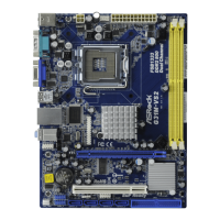
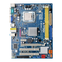
ASRock G31M-VS Motherboard
EnglishEnglish
EnglishEnglish
English
connect to the
power supply
connect to the SATA
HDD power connector
2.6 Onboard Headers and Connectors2.6 Onboard Headers and Connectors
2.6 Onboard Headers and Connectors2.6 Onboard Headers and Connectors
2.6 Onboard Headers and Connectors
Onboard headers and connectors are NOT jumpers. Do NOT place
jumper caps over these headers and connectors. Placing jumper caps
over the headers and connectors will cause permanent damage of the
motherboard!
Primary IDE connector (Blue)
(39-pin IDE1, see p.2 No. 8)
Note: Please refer to the instruction of your IDE device vendor for the details.
Serial ATAII Connectors These Serial ATAII (SATAII)
(SATAII_1: see p.2, No. 12) connectors support SATAII
(SATAII_2: see p.2, No. 11) or SATA hard disk for internal
storage devices. The current
SATAII interface allows up to
3.0 Gb/s data transfer rate.
Serial ATA (SATA) Either end of the SATA data cable
Data Cable can be connected to the SATA /
(Optional) SATAII hard disk or the SATAII
connector on the motherboard.
Serial ATA (SATA) Please connect the black end of
Power Cable SATA power cable to the power
(Optional) connector on each drive. Then
connect the white end of SATA
power cable to the power
connector of the power supply.
connect the black end
to the IDE devices
connect the blue end
to the motherboard
80-conductor ATA 66/100 cable
SATAII_1 SATAII_2
 Loading...