1313
1313
13
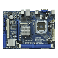
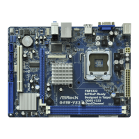
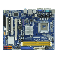
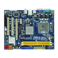
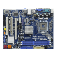
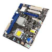
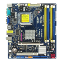
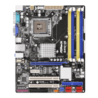
ASRock G41M-VGS3 / G41M-VS3 Motherboard
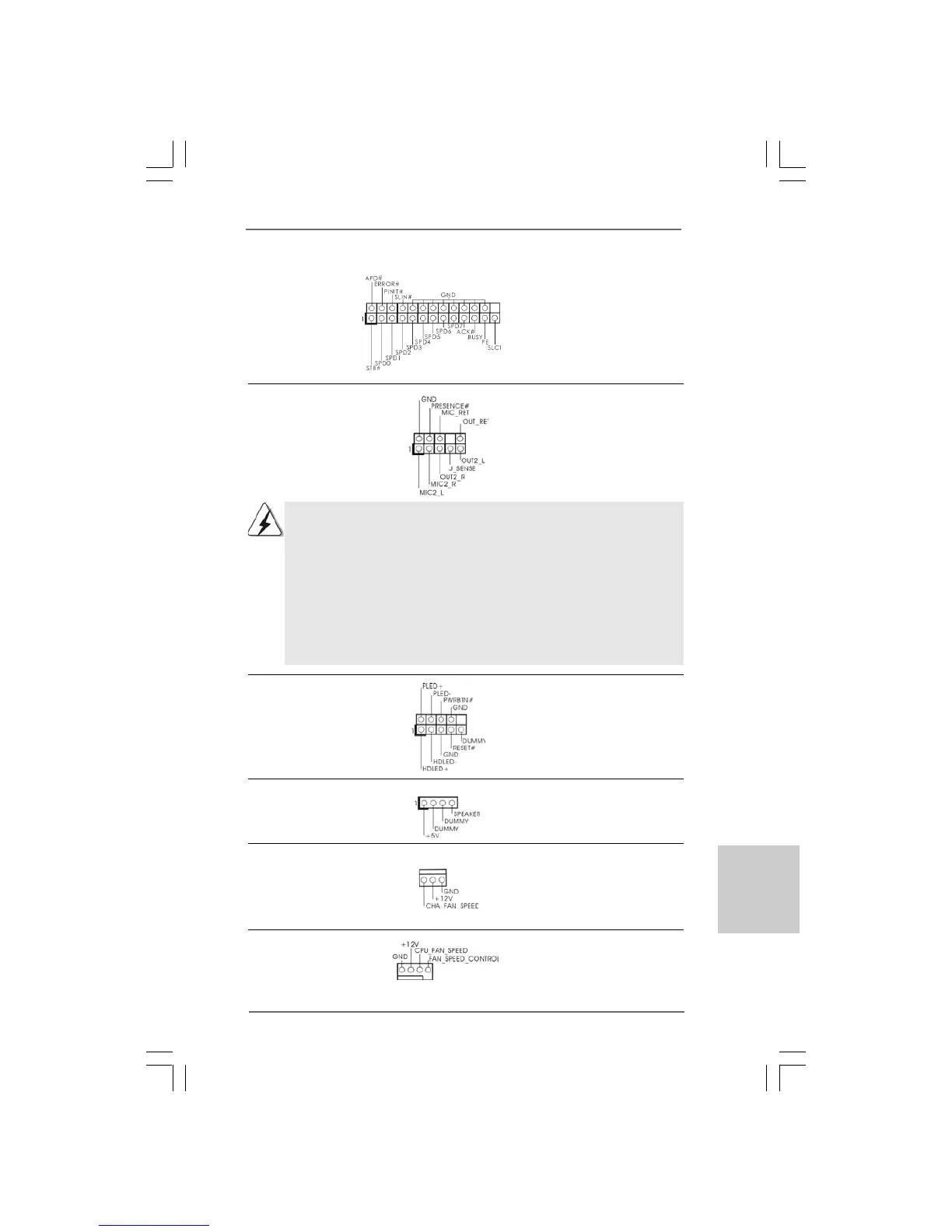
1. High Definition Audio supports Jack Sensing, but the panel wire on
the chassis must support HDA to function correctly. Please follow the
instruction in our manual and chassis manual to install your system.
2. If you use AC’97 audio panel, please install it to the front panel audio
header as below:
A. Connect Mic_IN (MIC) to MIC2_L.
B. Connect Audio_R (RIN) to OUT2_R and Audio_L (LIN) to OUT2_L.
C. Connect Ground (GND) to Ground (GND).
D. MIC_RET and OUT_RET are for HD audio panel only. You don’t
need to connect them for AC’97 audio panel.
Print Port Header This is an interface for print
(25-pin LPT1) port cable that allows
(see p.2 No. 26) convenient connection of printer
devices.
Front Panel Audio Header This is an interface for front
(9-pin HD_AUDIO1) panel audio cable that allows
(see p.2 No. 24) convenient connection and
control of audio devices.
EnglishEnglish
EnglishEnglish
English
System Panel Header This header accommodates
(9-pin PANEL1) several system front panel
(see p.2 No. 8) functions.
Chassis Speaker Header Please connect the chassis
(4-pin SPEAKER 1) speaker to this header.
(see p.2 No. 14)
Chassis Fan Connector Please connect a chassis fan
(3-pin CHA_FAN1) cable to this connector and
(see p.2 No. 16) match the black wire to the
ground pin.
CPU Fan Connector Please connect a CPU fan cable
(4-pin CPU_FAN1) to this connector and match
(see p.2 No. 3) the black wire to the ground pin.
1 2 3 4
 Loading...