EasyManua.ls Logo

ASROCK H110M-G/M.2 User Manual

ASROCK H110M-G/M.2
147 pages
To Next Page IconTo Next Page
Page #1 background imageLoading...
Page #1 background image
Version 1.0
Published April 2017
Copyright©2017 ASRock INC. All rights reserved.
Copyright Notice:
No part of this documentation may be reproduced, transcribed, transmitted, or
translated in any language, in any form or by any means, except duplication of
documentation by the purchaser for backup purpose, without written consent of
ASRock Inc.
Products and corporate names appearing in this documentation may or may not be
registered trademarks or copyrights of their respective companies, and are used only
for identication or explanation and to the owners’ benet, without intent to infringe.
Disclaimer:
Specications and information contained in this documentation are furnished for
informational use only and subject to change without notice, and should not be
constructed as a commitment by ASRock. ASRock assumes no responsibility for any
errors or omissions that may appear in this documentation.
With respect to the contents of this documentation, ASRock does not provide
warranty of any kind, either expressed or implied, including but not limited to the
implied warranties or conditions of merchantability or tness for a particular purpose.
In no event shall ASRock, its directors, ocers, employees, or agents be liable for any
indirect, special, incidental, or consequential damages (including damages for loss
of prots, loss of business, loss of data, interruption of business and the like), even if
ASRock has been advised of the possibility of such damages arising from any defect or
error in the documentation or product.
is device complies with Part 15 of the FCC Rules. Operation is subject to the following two
conditions:
(1) this device may not cause harmful interference, and
(2) this device must accept any interference received, including interference that may cause
undesired operation.
CALIFORNIA, USA ONLY
e Lithium battery adopted on this motherboard contains Perchlorate, a toxic substance
controlled in Perchlorate Best Management Practices (BMP) regulations passed by the Cali-
fornia Legislature. When you discard the Lithium battery in California, USA, please follow
the related regulations in advance.
“Perchlorate Material-special handling may apply, see
www.dtsc.ca.gov/hazardouswaste/perchlorate
ASRock Website: http://www.asrock.com
Question and Answer IconNeed help?

Do you have a question about the ASROCK H110M-G/M.2 and is the answer not in the manual?

ASROCK H110M-G/M.2 Specifications

General IconGeneral
BrandASROCK
ModelH110M-G/M.2
CategoryMotherboard
LanguageEnglish

Summary

Motherboard Layout and Components

Component Identification Diagram

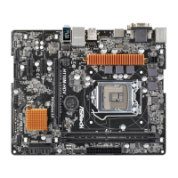
Diagram illustrating the location of motherboard components with numerical labels.

Motherboard Component Descriptions

I/O Panel Overview

Rear Panel I/O Ports Identification

Diagram and list identifying all rear panel input/output ports.

1.2 Specifications

Platform, CPU, and Chipset Specifications

Details on motherboard form factor, CPU support, and chipset.

Memory and Expansion Slot Specifications

Information on DDR4 memory support and PCI Express slot types.

Graphics and Visuals Specifications

Details on integrated Intel HD Graphics features and output options.

Specifications Continued

Audio and LAN Specifications

Details on 7.1 CH HD Audio, surge protection, and Gigabit LAN features.

Onboard Connectors and Storage

Rear Panel I/O and Internal Connectors

List of rear panel ports and internal headers like fan, power, and USB.

Chapter 2: Installation

Pre-installation Safety Precautions

Essential safety guidelines and precautions before installing components.

2.1 Installing the CPU

CPU Socket Preparation and Insertion

Step-by-step instructions and diagrams for installing the CPU into the socket.

CPU Installation Process

Securing the CPU with Socket Lever

Diagrams illustrating securing the CPU with the socket lever.

2.2 Installing the CPU Fan and Heatsink

CPU Cooler Mounting Procedure

Diagrams showing the process of applying thermal paste and mounting the CPU cooler.

2.3 Installing Memory Modules (DIMM)

DIMM Installation Best Practices

Rules for installing DDR4 DIMMs for dual channel and correct orientation.

DIMM Installation Steps

2.4 Expansion Slots (PCI Express Slots)

PCI Express Slot Usage Guidelines

Description of each PCI Express slot (PCIE1, PCIE2, PCIE3) and their intended use.

2.5 Onboard Headers and Connectors

Onboard Connectivity Details

Onboard Audio and Fan Connectors

Power and System Interface Connectors

2.6 M.2_SSD (NGFF) Module Installation Guide

M.2 SSD Module Installation Steps

Steps for installing an M.2 SSD module, including nut location selection.

M.2 SSD Installation Procedure

Enabling USB Ports for Windows 7 Installation

Related product manuals