25
English
H570M-IT X/ac
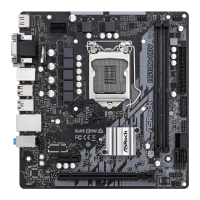
CPU Fan Connector
(4-pin CPU_FAN1)
(see p.7, No. 2)
is motherboard pro-
vides a 4-Pin CPU fan
(Quiet Fan) connector.
If you plan to connect a
3-Pin CPU fan, please
connect it to Pin 1-3.
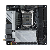
ATX Power Connector
(24-pin ATXPWR1)
(see p.7, No. 5)
is motherboard pro-
vides a 24-pin ATX power
connector.
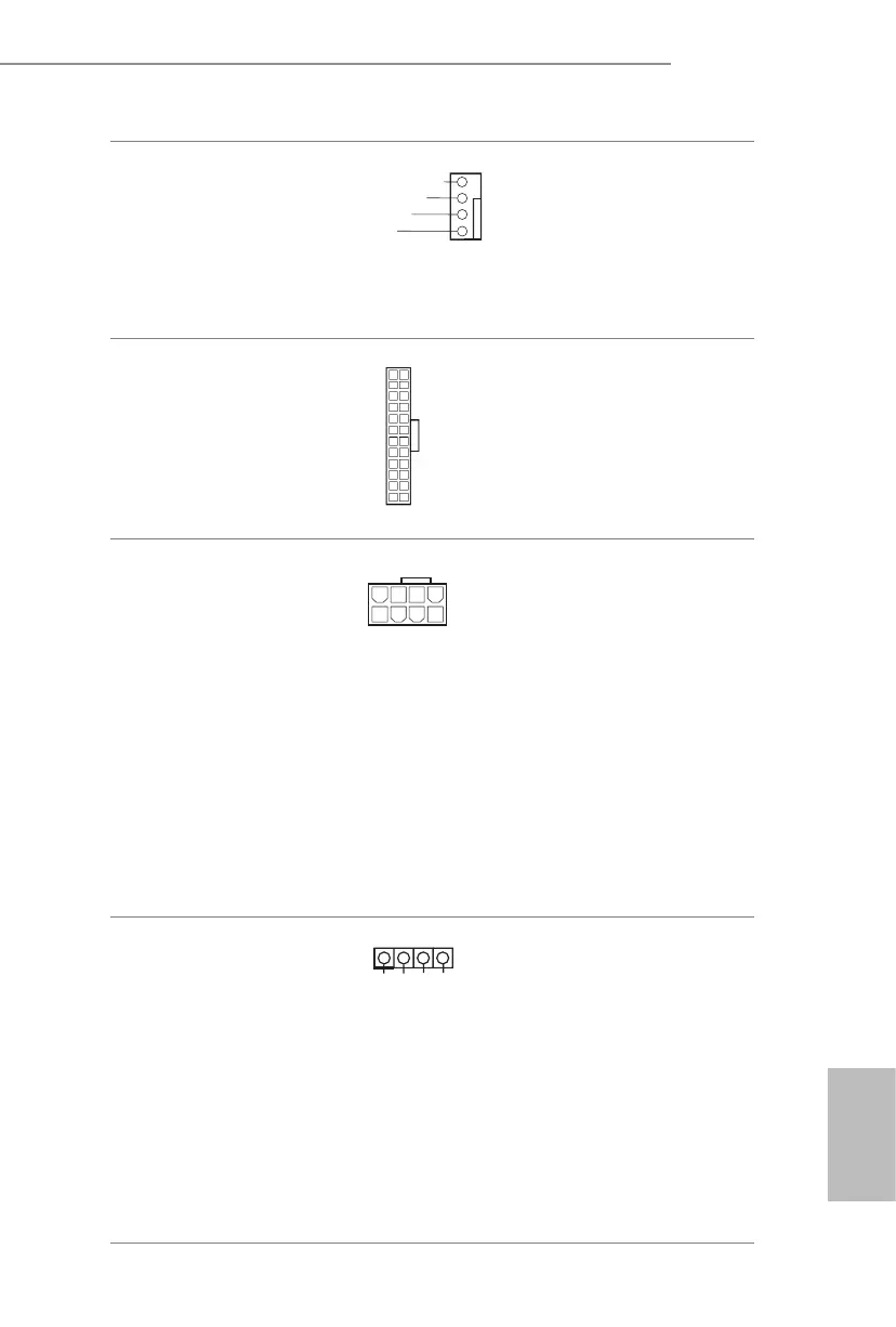
ATX 12V Power
Connector
(8-pin ATX12V1)
(see p.7, No. 3)
is motherboard
provides a 8-pin ATX 12V
power connector. To use a
4-pin ATX power supply,
please plug it along Pin 1
and Pin 5.
*Warning: Please make
sure that the power cable
connected is for the CPU
and not the graphics
card. Do not plug the
PCIe power cable to this
connector.
RGB LED Header
(4-pin RGB_LED1)
(see p.7, No. 18)
RGB header is used to connect
RGB LED extension cable which
allows users to choose from vari-
ous LED lighting eects.
Caution: Never install the RGB
LED cable in the wrong orienta-
tion; otherwise, the cable may
be damaged.
* Please refer to page 43 for
further instructions on this
header.
FAN_SPEED
FAN_SPEED_CONTROL
+12V
GND
4
2
3
1
12
1
24
13
4
1
12V G R B
1
 Loading...