Do you have a question about the ASROCK H610M-H2/M.2 D5 and is the answer not in the manual?
Lists the items included in the motherboard package, such as the motherboard, manual, I/O shield, and SATA cables.
Provides technical specifications for platform, CPU, chipset, memory, expansion slots, graphics, and audio.
Details LAN, USB, rear panel I/O, storage connectors, and BIOS features of the motherboard.
Outlines supported operating systems and lists relevant certifications like FCC and CE for the motherboard.
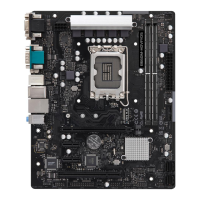
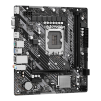
Visual diagram identifying the placement of key components and connectors on the motherboard.
Details the rear I/O panel ports, including USB, LAN, audio, and HDMI, with LED indicators for LAN.
Illustrates the internal architecture and data flow between the CPU, chipset, and various I/O components.
Essential safety guidelines and precautions to follow before installing motherboard components to prevent damage.
Step-by-step instructions for correctly installing the CPU into the motherboard socket, including visual aids.
Guide on how to properly install the CPU cooling fan and heatsink onto the motherboard.
Instructions for installing DDR5 DIMM memory modules, emphasizing dual-channel configuration and correct orientation.
Details on connecting the system panel header for power buttons, LEDs, and reset switches to the motherboard.
Instructions for installing the I/O panel shield into the computer chassis before mounting the motherboard.
Guidance on securely mounting the motherboard into the computer chassis using screws.
Steps for installing SATA drives (like HDDs or SSDs) and connecting them using SATA data and power cables.
Instructions on how to install a graphics card into the appropriate PCIe slot on the motherboard.
Explanation of the available PCIe slots (PCIE1, PCIE2) and their usage for expansion cards.
Illustrates how to connect common peripheral devices like monitors, keyboards, and mice to the I/O panel.
Guide for connecting the ATX 12V and ATX power connectors from the PSU to the motherboard.
Steps to safely power on the computer after all components have been installed.
Explains the function and usage of the Clear CMOS jumper (CLRMOS1) for resetting BIOS settings.
Details on connecting the system panel header for power buttons, LEDs, and audio connectors.
Describes the Chassis Intrusion/Speaker header and the various SATA3 connectors for storage devices.
Explains the pinouts and functionality of the USB 2.0 and USB 3.2 Gen1 headers for front panel USB ports.
Details for connecting the front panel audio header and chassis/water pump fan connectors.
Instructions for connecting the CPU fan header and the main 24-pin ATX power connector.
Explains the ATX 12V power connector and the SPI TPM header for security module connection.
Step-by-step guide for installing an M.2 SSD module into the motherboard's M.2 slot.
| Processor socket | LGA 1700 |
|---|---|
| Processor manufacturer | Intel |
| Compatible processor series | - |
| Maximum number of SMP processors | 1 |
| Memory channels | Dual-channel |
| Memory slots type | DIMM |
| Number of memory slots | 2 |
| Supported memory types | DDR5-SDRAM |
| Maximum internal memory | 96 GB |
| Supported storage drive interfaces | M.2, SATA III |
| TPM connector | Yes |
| Number of SATA III connectors | 4 |
| USB 3.2 Gen 2 (3.1 Gen 2) connectors | 0 |
| USB 2.0 ports quantity | USB 2.0 ports have a data transmission speed of 480 Mbps, and are backwards compatible with USB 1.1 ports. You can connect all kinds of peripheral devices to them. |
| Wi-Fi | No |
| LAN controller | Realtek 8111H |
| Ethernet interface type | Gigabit Ethernet |
| Component for | PC |
| Motherboard chipset | Intel H610 |
| Audio output channels | 7.1 channels |
| Motherboard form factor | micro ATX |
| Windows operating systems supported | Windows 10 x64, Windows 11 x64 |
| BIOS type | UEFI AMI |
| BIOS memory size | 128 Mbit |
| Depth | 193 mm |
|---|---|
| Width | 220 mm |