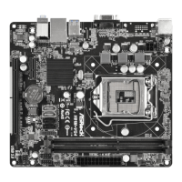
Chassis Fan Connector
(4-pin CHA_FAN1)
(see p.1, No. 11)
Please connect fan cable
to the fan connector and
match the black wire to
the ground pin.
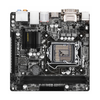
CPU Fan Connectors
(4-pin CPU_FAN1)
(see p.1, No. 6)
is motherboard pro-
vides a 4-Pin CPU fan
(Quiet Fan) connector.
If you plan to connect a
3-Pin CPU fan, please
connect it to Pin 1-3.
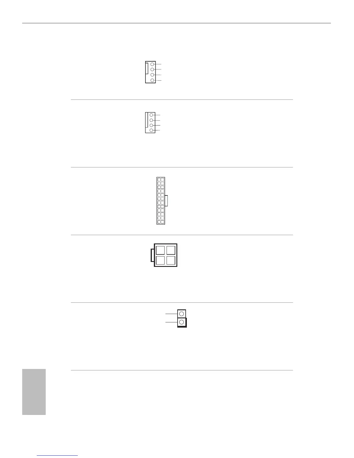
ATX Power Connector
(24-pin ATXPWR1)
(see p.1, No. 5)
is motherboard pro-
vides a 24-pin ATX power
connector. To use a 20-pin
ATX power supply, please
plug it along Pin 1 and Pin
13.
ATX 12V Power
Connector
(8-pin ATX12V1)
(see p.1, No. 1)
is motherboard pro-
vides an 8-pin ATX 12V
power connector. To use a
4-pin ATX power supply,
please plug it along Pin 1
and Pin 5.
Chassis Intrusion Header
(2-pin CI1)
(see p.1, No. 4)
is motherboard supports
CASE OPEN detection feature
that detects if the chassis cove
has been removed. This feature
requires a chassis with chassis
intrusion detection design.
 Loading...