17
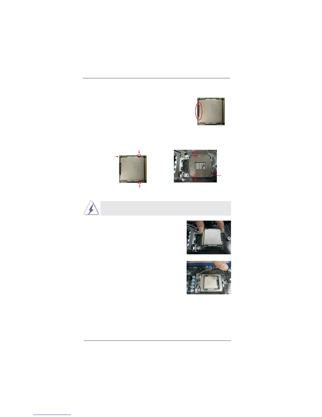
Pin1
alignment key
alignment key
Pin1
1156-Pin CPU
1156-Pin Socket
Step 3. Insert the 1156-Pin CPU:
Step 3-1. Hold the CPU by the edge where is
marked with black line.
Step 3-2. Orient the CPU with IHS (Integrated
Heat Sink) up. Locate Pin1 and the
two orientation key notches.
For proper inserting, please ensure to match the two orientation key
notches of the CPU with the two alignment keys of the socket.
Step 3-3. Carefully place the CPU into the
socket by using a purely vertical mo-
tion.
Step 3-4. Verify that the CPU is within the sock-
et and properly mated to the orient
keys.
Step 4. Close the socket:
Step 4-1. Rotate the load plate onto the IHS.
Step 4-2. While pressing down lightly on load
plate, engage the load lever.
orientation key notch
orientation key notch
black line
 Loading...