24
Infrared Module Header This header supports an
(5-pin IR1)
optional wireless transmitting
(see p.12 No. 29)
and receiving infrared module.
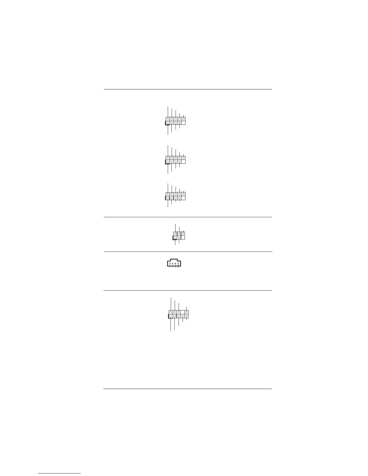
USB 2.0 Headers Besides six default USB 2.0
(9-pin USB8_9)
ports on the I/O panel, there
(see p.12 No. 27)
are three USB 2.0 headers on
this motherboard. Each
USB 2.0 header can support
two USB 2.0 ports.
(9-pin USB10_11)
(see p.12 No. 26)
(9-pin USB12_13)
(see p.12 No. 25)
1
IRTX
+5VSB
DUMMY
IRRX
GND
1
DUMMY
GND
P+13
P-13
USB_PWR
USB_PWR
GND
P+12
P-12
1
USB_PWR
P-8
GND
DUMMY
USB_PWR
P+8
GND
P-9
P+9
1
USB_P WR
P-10
GND
DUMMY
USB_P WR
P+10
GND
P-11
P+11
J_SENSE
OUT2_L
1
MIC_RET
PRESENCE#
GND
OUT2_R
MIC2_R
MIC2_L
OUT_RET
Front Panel Audio Header This is an interface for front
(9-pin HD_AUDIO1)
panel audio cable that allows
(see p.12 No. 32)
convenient connection and
control of audio devices.
Internal Audio Connectors This connector allows you
(4-pin CD1)
to receive stereo audio input
(CD1: see p.12 No. 33)
from sound sources such as
a CD-ROM, DVD-ROM, TV
tuner card, or MPEG card.
CD1
CD-L
GND
GND
CD-R
 Loading...