1010
1010
10
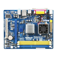
1.3 Motherboard Layout1.3 Motherboard Layout
1.3 Motherboard Layout1.3 Motherboard Layout
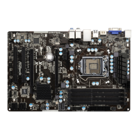
1.3 Motherboard Layout
1 PS2_USB_PWR1 Jumper 11 USB_PWR3 Jumper
2 Chassis Fan Connector (CHA_FAN1) 12 PCI Slot (PCI1)
3 CPU Fan 13 USB 2.0 Header (USB6_7, Blue)
4 CPU Heatsink 14 Primary SATAII Connector (SATAII_1; Blue)
5 VIA VX900 A3 Chipset 15 Front Panel Audio Header
6 2 x 240-pin DDR3 DIMM Slots (HD_AUDIO1, White)
(DDR3_1, DDR3_2; Blue) 16 Secondary SATAII Connector (SATAII_2; Blue)
7 ATX Power Connector (ATXPWR1) 17 USB 2.0 Header (USB4_5, Blue)
8 System Panel Header (PANEL1, White) 18 Clear CMOS Jumper (CLRCMOS1)
9 Chassis Speaker Header (SPEAKER 1, White) 19 USB_PWR2 Jumper
10 BIOS SPI Chip 20 CPU Fan Connector (CPU_FAN1)
PS2
Mouse
PS2
Keyboard
PARALLEL PORT
VGA1
COM1
USB 2.0
T: USB0
B: USB1
Top:
RJ-45
USB 2.0
T: USB2
B: USB3
Top:
Line In
Center:
Line Out
Bottom:
Mic In
17.0cm (6.7 in)
17.0cm (6.7 in)
FSB800
DDR3_1 (64 bit, 240-pin module)
FSB800
DDR3_2 (64 bit, 240-pin module)
PV530A-ITX
ErP/EuP Ready
4Mb
BIOS
CMOS
Battery
Super
IO
PCI1
SATAII_1
SATAII_2
1
USB6_7
1
USB4_5
CLRCMOS1
AUDIO
CODEC
LAN
PHY
HD_AUDIO1
1
SPEAKER1
1
PANE L 1
HDLED RESET
PLED PWRBTN
1
CHA_FAN1
CPU_FAN1
1
PS2_USB_PWR1
DDR3
Designed in Taipei
1
USB_PWR2
RoHS
1
USB_PWR3
1
2
4
5
7
6
3
8
910
12
13
14
11
15
16
17
18
19
20
 Loading...