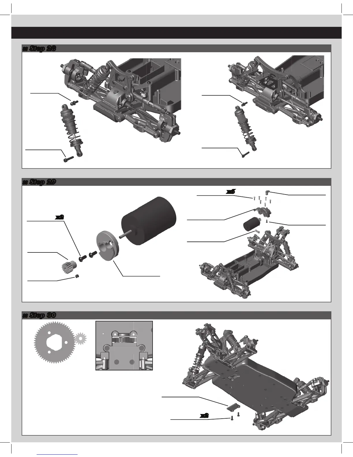
:: Step 29
:: Step 30
15
:: Step 28
x2
x6
x2
31520
M2.5x6mm
BHCS
21546
M2.6x10mm
BHST, silver
21546
M2.5x8mm
FHST
21501
Bottom spur
cap (58T)
21522
Ball stud
12.5mm
21522
Ball stud
12.5mm
8691
M2.5x12mm
SHCS
21532
Pinion
gear, 16T
31500
M3x2.5mm
set screw
8691
M2.5x12mm
SHCS
Build x2 (right and left side)
21531
Motor mount
cam
21546
M2.6x8mm
BHST
21504
Body mount,
rear
21531
Motor mount
insert
21504
Center diff
cap
Set The Gear Mesh:
To set the gear mesh, push the teeth of the motor
mount cam #21531 into the corresponding tooth
pattern of the motor mount insert. Once the teeth
are seated, you should be able to rock the spur gear
back and forth without making the pinion gear move.
Exessive amounts of spur gear movement (loose
gear mesh) will cause premature gear failure. If the
spur gear mesh is tight, there will be no movement
between the spur and pinion gears. A gear mesh that
is too tight or too loose will reduce power and
damage the gear teeth.