Do you have a question about the Associated Electrics RC8B4.1e Team Kit and is the answer not in the manual?
Welcome and overview of the assembly manual for the RC8B4.1e kit.
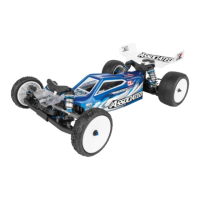
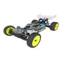
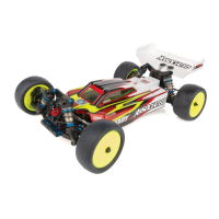
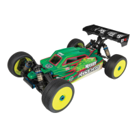
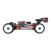
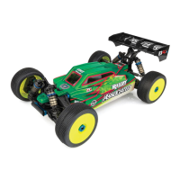
Highlights of the RC8B4.1e including chassis, suspension, drivetrain, and electronics design.
Visual reference for screws, nuts, and bearings with 1:1 scale views for easy identification.
Explanation of symbols used for notes, build order, and racer's tips within the manual.
Finalizing the front and rear differential assembly with diff fluid and alignment checks.
Beginning the center differential assembly, including gearset selection and alignment.
Completing the center differential build with diff fluid and specific tips.
Starting the shock build process, focusing on pistons, shafts, and core components.
Assembling shock caps, boots, rod ends, and performing fluid filling and bleeding.
Mounting shock springs, collars, and cups, noting spring identification marks.
Building the servo and steering turnbuckles with rod ends and balls.
Constructing the rear hub turnbuckles, ensuring proper rod end and ball placement.
Attaching chassis parts, side guards, and assembling the servo saver mechanism.
Building the steering bellcrank with bearings, shims, and pivot balls.
Completing steering assembly with rack, nut, and thread lock.
Building the front gearbox halves, including pinion gear, outdrive, and gear mesh.
Installing arm mounts, hinge pins, and droop screws for suspension setup.
Attaching anti-roll bar links and pivots, adjusting gap for smooth rotation.
Tightening anti-roll bar set screws and attaching front body posts.
Mounting front shock towers and upper arm mounts for suspension.
Adding caster clips and adjusting suspension arm spacing for optimal rotation.
Building steering blocks with bearings, hubs, and pillow ball assemblies.
Installing pillow ball shims, front bumper, and attaching steering link.
Mounting front shocks into the suspension arms and securing with locknuts.
Assembling rear gearbox halves, pinion gear, outdrive, and adjusting gear mesh.
Installing rear arm mounts and inserts into the gearbox housing.
Attaching rear suspension arms, anti-roll bar links, and pivots.
Securing anti-roll bar set screws and aligning pivot balls for free movement.
Installing chassis braces, body posts, and wing components for stability.
Mounting rear body posts and wing adapter, considering wing height position.
Building rear hubs with plates, bearings, and set screws.
Installing rear shocks and mounting hubs, ensuring proper fit and function.
Assembling center bulkheads, adapter plates, and securing dogbones.
Installing center dogbones and attaching wire routing clips to the chassis.
Mounting motor mounts and optional fan, ensuring secure installation.
Installing servo splines, receiver box, and wire clips for the radio system.
Attaching upper receiver box and servo horn, noting spline count.
Steps for configuring the chassis for 2s or 4s shorty battery packs.
Configuring ESC, tray spacer, and straps for 2s shorty battery packs.
Setting up the chassis for 4s shorty battery packs using the ESC tray.
Correctly installing wheel nuts with serrated edge towards the wheel.
Preparing the polycarbonate body for painting and cutting along trim lines.
Measuring and adjusting front and rear droop screws for optimal suspension performance.
Guidance on finding and applying setup sheets for vehicle tuning and optimization.
| Brand | Associated Electrics |
|---|---|
| Model | RC8B4.1e Team Kit |
| Category | Motorized Toy Car |
| Language | English |